Repair ZIL-5301
The ZIL-5301 "Bychok" is a light-duty truck whose specifications vary depending on the model, but generally speaking, it features a 4.75-liter diesel engine (producing between 109 and 130 hp), a payload capacity of approximately 3–3.5 tons, and a top speed of 95 km/h.
Key features include rear-wheel drive, a five-speed manual transmission, and reinforced suspension with leaf springs.
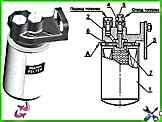
Replacing the fine fuel filter
The service life of the fine fuel filter depends on the purity of the fuel used

Electrical diagram of the electro-pneumatic door drive ZIL-5301
An electro-pneumatic door closing drive is used on buses and special vehicles. The electrical diagram of the drive is shown below