Repair ZIL-5301
The ZIL-5301 "Bychok" is a light-duty truck whose specifications vary depending on the model, but generally speaking, it features a 4.75-liter diesel engine (producing between 109 and 130 hp), a payload capacity of approximately 3–3.5 tons, and a top speed of 95 km/h.
Key features include rear-wheel drive, a five-speed manual transmission, and reinforced suspension with leaf springs.
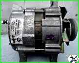
ZIL-5301 vehicles and its modifications are equipped with an alternating current generator mod. 2022.3701, ZIL buses are equipped with an alternating current generator mod. 3882.3701
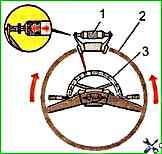
Check the angular free play of the steering wheel with the engine idling, shaking the steering wheel until the steering wheels begin to turn
")

")
")
")
")
")
")
")