Repair ZIL-5301
The ZIL-5301 "Bychok" is a light-duty truck whose specifications vary depending on the model, but generally speaking, it features a 4.75-liter diesel engine (producing between 109 and 130 hp), a payload capacity of approximately 3–3.5 tons, and a top speed of 95 km/h.
Key features include rear-wheel drive, a five-speed manual transmission, and reinforced suspension with leaf springs.
ZIL-5301 rear axle gearbox
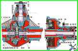
The car and bus are equipped with a leading rear axle with a single-stage hypoid final drive (Fig. 1).
The final drive ratio is 3.273 or 3.45.
The differential is a bevel gear with four satellites.
The final drive can be adjusted or repaired without removing the rear axle from the vehicle.
The preload of the final drive bearings, the lateral clearance in the engagement and the contact patch are adjusted at the factory and, as a rule, they do not require adjustment during operation.
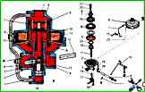
The brake force regulator (Fig. 1) automatically regulates the pressure of compressed air supplied to the brake chambers of the rear wheels during braking in accordance with the current axial load
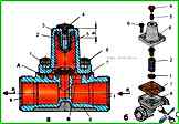
Features of the design of the single safety valve ZIL-5301
The single safety valve (Fig. 1) serves to protect the vehicle's brake drive from loss of compressed air in the event of damage to the connecting lines, compressed air consumers that are not related to the brake system
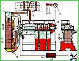
The diagram of the diesel liquid cooling system with forced circulation of coolant from a centrifugal pump is shown in Figure 1

Adjusting the thrust bearings of the ZIL-5301 steering gear
To adjust the bearings, do the following:
")

")
")
")
")
")
")
")