ZIL-5301 wiring diagram
For better clarity, the diagram is divided into 2 parts.
You can enlarge the diagram by opening it in another browser window.
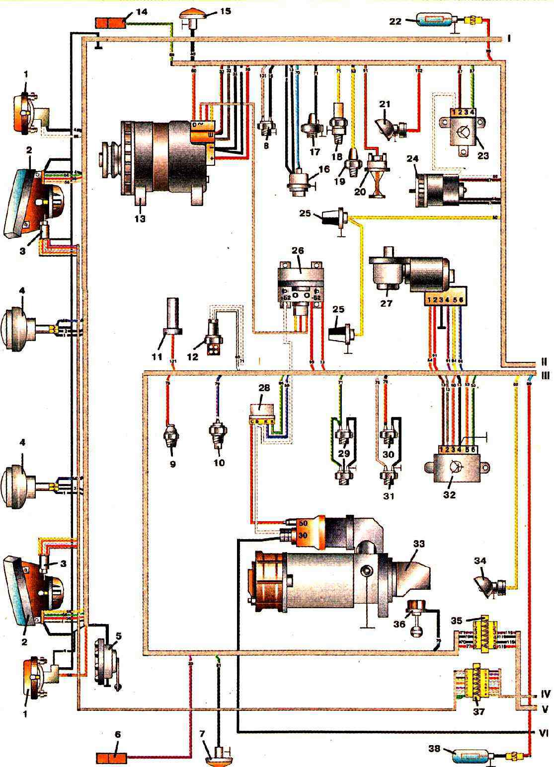
Part 1
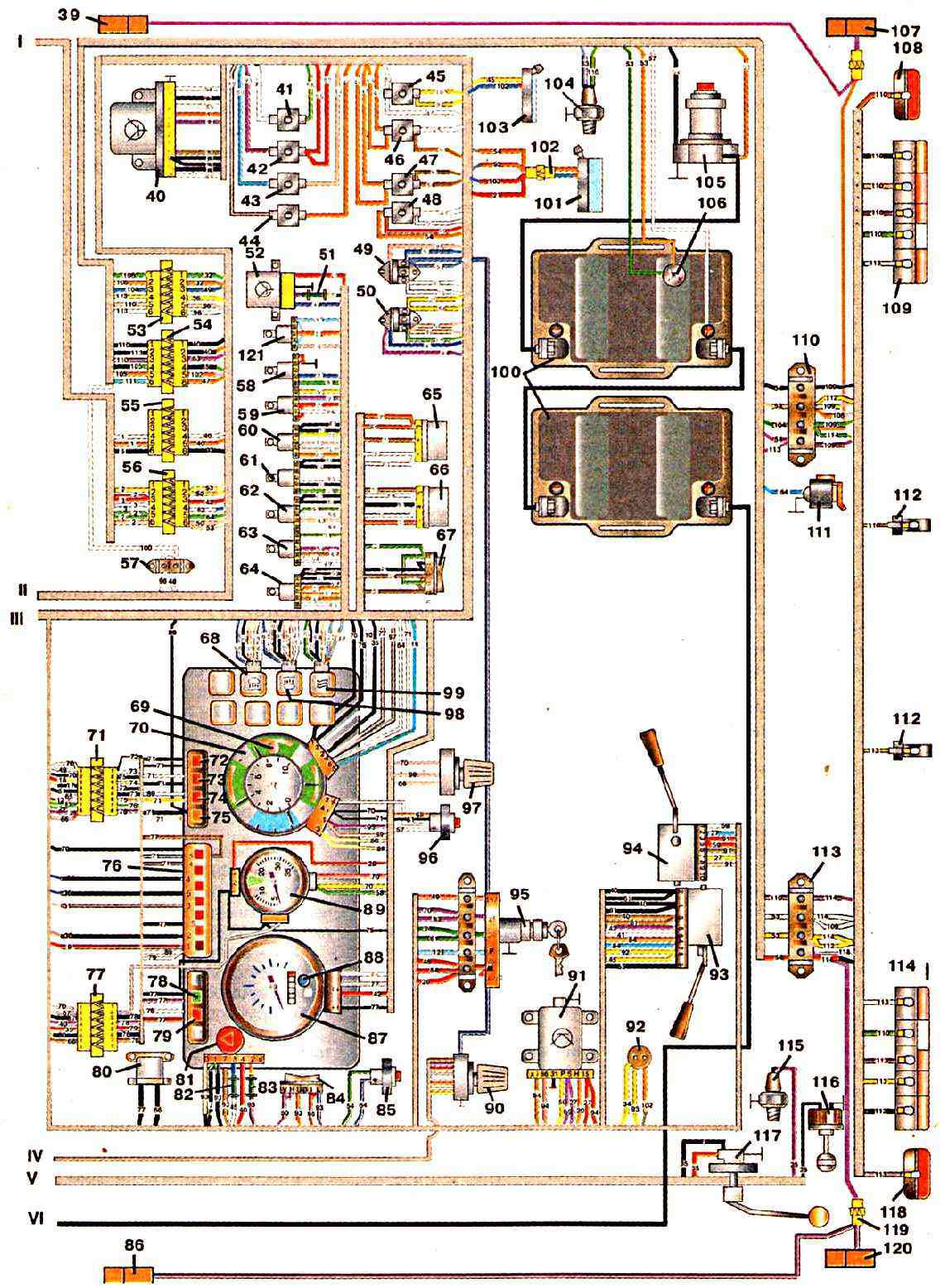
Part Two of the Diagram
General Diagram
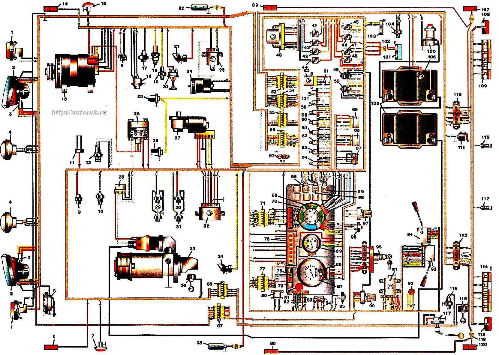
Explanations for the diagram: 1 - front left turn signals 4619.3726 and right 4609.3726; 5 - electric horn 20.3721-01 or C3-3B; 9 - coolant overheating alarm sensor TM111; 13 - generator 2022.3771; 19 - coolant level alarm sensor DKU1M; 23 - electronic fan speed controller ROV2MS; 27 - windshield wiper motor 35.5205; 32 - voltage regulator 42.3702 or 206-3702 or 207.3702; 39 and 86 - side middle marker lights 43.3731; 46 - push-button thermal bimetallic fuse for 20 A 129.3722; 57, 110 and 113 - connecting panels; 61 - relay for switching on the spark plug of the electric torch device 111.3747 or 90.3747, or 851.3747; 65 - thermal relay of the electric torch device 12.3741; 69 - generator set status indicator; 74 - oil pressure drop indicator 2202.3803-23; 79 - reserve fuel indicator 2202.3803-19; 85 - remote switch of storage batteries 11.3704; 90 - electric corrector control unit BUK021; 94 - windshield wiper switch 9912.3709; 98 - rear fog light switch 3832.3710-02.04; 103 - cabin light PK142; 107 and 120 - side rear marker lights 43.3731; 112 - license plate lights FP134; 2 - headlights 6002/6012.3711 or 68/681.3711; 6 and 14 - side front marker lights 43.3731; 10 - coolant temperature sensor TM100-V or 2442.38.28 or TM100V-01 or TM100V-K; 16 - oil pressure indicator sensor 18.3829 or MM355; 20 - windshield washer electric motor 11.5208; 24 - cabin heater electric motor ME272-B; 28 - starter contactor 59.3747; 33 - starter 20.3708 or ST142N; 40 - turn signal interrupter RS950S; 48 - 30 A push-button thermal bimetallic fuse 291.3722; 58 - starter automatic shutdown relay 111.3747-10 or 90.3747-22 or 853.3747; 62 - fog lamp and rear fog lamp relay 111.3747, or 90.3747, or 851.3747; 66 - parking brake indicator switch PC492; 70 - instrument cluster 36.3801; 75 - electric torch device activation indicator 2202.3803-17; 80 - brake system malfunction buzzer 733.3747-01; 87 - speedometer 48.3802; 91 - windshield wiper and washer electronic control unit 92.3761 (installed on buses); 95 - instrument and starter switch 20.3704; 99 - rear-view mirror heating element switch 3802.3710-02.23; 108 and 118 - rear side lights 35.3731; 3 - headlight corrector electric drive EPKO22; 7 and 15 - side turn signal lights 5702.3726; 11 - fuel supply cut-off electromagnet; 17 - air filter clogging indicator sensor 13.3839; 21 and 34 - underhood lamps PD308-A; 25 - front contour lights 36.3731; 29 - front and rear brake signal switches 2802.3829 or 3402.3829; 35,37,53,54,55,56,71,77, 102 and 119 - connecting terminals; 41, 43, 44 45 and 47 - push-button thermal bimetallic fuses for 10 A 292.3702; 49 and 50 - blocks of thermal bimetallic push-button fuses 13.3722-01 for 7.5 Ax2; 51, 82 and 183 - fuses, respectively, 2 APR118B-01, 6 A PRII9-01 and 10APR119B-01; 59 - windshield wiper control relay 111.3747 or 90.3747; 63 - brake signal relay 111.3747, or 90.3747, or 851.3747; 67 - cabin heater switch 11147-04.11; 72 - air filter clogging indicator 2202.3803-20; 76 - brake system control indicator unit 2302.3803-21; 81 - hazard warning light switch 24.3710; 88 - headlight high beam indicator; 92 - portable lamp socket 47K-0; 96 - electric torch device switch 11.3704-01; 100 - storage batteries 6ST-11OAZ; 104 - reversing light switch B3X-1 or BK403 or 5217.3710 or B12.3710; 105 - remote battery switch 1312.3737; 109 and 114 - left, respectively th and right rear lights 1711.3716 or 1102.3736; 115 - parking brake indicator sensor MM24d or 2702.3829; 116 - switch for critical drop in brake fluid level indicator in rear axle brake hydraulic reservoir; 121 - anti-theft device relay 111.3747, or 90.3747, or 851.3747; 4 - fog lights FG 152-AB; 8 - anti-theft device switch 2802.3829 or 3402.3829; 12 - spark plug of the electric torch device EFP-8101500; 18 - sensor of emergency oil pressure indicator 2602.3829 or B10.3829 or 3202.3829 or DE-M; 22 and 38 - mirror heaters; 26 - transformer-rectifier unit 1212.3759 or 3797.001; 30 and 31 - sensors of drop in air pressure in the circuit of front and rear brakes 2702.3829; 36 - switch of indicator of critical drop in level of brake fluid in the hydraulic drive reservoir of the front axle brakes; 42 - push-button thermal bimetallic fuse for 15 A293.3702; 52 - electronic unit of coolant level indicator in engine cooling system SKU1.MS; 60 - generator excitation winding cut-off relay 111.3747 or 90.3747; 64 - heater relay 111.3747, or 90.3747, or 851.3747; 68 - fog light switch 3802.3710-02.03 (if installed); 73 - critical coolant level indicator in engine cooling system; 78 - turn signal indicator 2202.3803-07; 84 - side light and headlight switch P147-07.04; 89 - tachometer 2541.3813; 93 - combination light switch 1112.3769; 97 - variable resistor VK41 6-B-01; 101 - cabin light 111.3714 or 0026.02.3714; 106 - electrolyte temperature sensor; 111 - PS400 portable lamp socket; 117 - fuel level indicator sensor 5302.3827; Note. The numbers on the wires indicate the position numbers of the units to which they are connected via the wiring harness
")

")
")
")
")
")
")
")