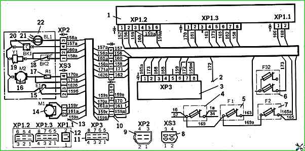
Diagnostics and repair of the ZIL-5301 heater
A decrease in the indicator line on the indicator status diagram shows the state of its extinction (for the PZhD8 heater)
If malfunctions occur, follow the following recommendations for their correction.

If the air blower is faulty, disconnect the air blower wire connector, unscrew the thermal fuse casing fastening nut and remove the casing; unscrew the screw of the air blower clamp, separate the halves of the clamp and remove the air blower.
Assembly must be done in the reverse order.
If the additional resistor is faulty, disconnect the wires from the terminals of the additional resistor, unscrew the M5 screws, remove the wire connecting the elements of the automatic system to the ground, and dismantle the additional resistor from the air supply pipe.
Assembly in the reverse order.
If the glow plug is faulty, use an S=8 wrench to unscrew the wire fastening nut, remove the spring and flat washers, the current-supply wire, the pressure washer, and the insulating washer.
Remove the ground wire and unscrew the glow plug with an S=19 wrench.
Assembly in the reverse order.
If the indicator is faulty, flame, disconnect the wire connectors, unscrew two screws, remove the cover, gasket and flame indicator with housing and gasket.
Assemble in reverse order.
If the temperature sensor is faulty, disconnect the sensor wire connector with a S=19 key and unscrew the sensor.
Assemble in reverse order.
If the thermal fuse is faulty, unscrew the thermal fuse casing fastening nut and remove the casing, remove the wires from the thermal fuse terminals and unscrew it.
Assemble in reverse order.
If the fuel pump is faulty, disconnect the solenoid wire, loosen the fuel line fastening clamps and remove them.
Unscrew the two fuel pump fastening screws, disconnect the ground wire and remove the fuel pump.
Assemble in reverse order.


