The diesel engine lubrication system, in accordance with Figures 1 and 2, is combined: some parts are lubricated under pressure, some by splashing
The crankshaft and camshaft bearings, the intermediate gear bushing, the compressor crankshaft connecting rod bearing, the valve drive mechanism (rocker arms) and the turbocharger shaft bearing are lubricated under pressure from the oil pump.
The liners, pistons, piston pins, rods, tappets, camshaft cams and fuel pump drive are lubricated by splashing.
The oil pump of the lubrication system is a gear type, single-section, bolted to the cover of the first main bearing.
The oil pump is driven by a gear installed on the crankshaft.
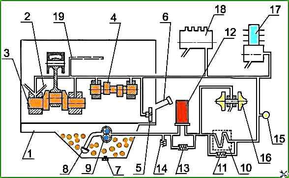
On diesel engines with a non-separable oil filter with a paper filter element and an oil radiator installed as part of the vehicle, - a diagram of the lubrication system in accordance with Figure 1.
Oil pump 9 takes oil from oil sump 1 through oil receiver 8 and feeds it through channels in the cylinder block and channels of the oil filter housing to full-flow oil filter 12, where it is cleaned of foreign impurities, wear products and oil decomposition products due to heating and oxidation.
From the oil filter, the purified oil enters radiator 10 for cooling.
From the oil radiator, the oil enters the oil line of the diesel engine.
When starting the diesel engine on cold oil, when the resistance to the passage of oil through the oil filter exceeds 0.13-0.17 MPa, the bypass valve 13 of the oil filter opens, the bypass (radiator) valve 11 of the oil radiator also opens, and the oil, bypassing the oil filter and oil radiator, enters the oil line.
A safety adjustable valve 14 is built into the filter housing. It is designed to maintain the oil pressure in the main oil line of 0.25-0.35 MPa.
Excess oil is drained through the valve into the diesel crankcase.
In case of excessive clogging of the filter paper, when the resistance of the oil filter becomes higher than 0.13-0.17 MPa, the bypass valve of the oil filter also opens, and the oil, bypassing the oil filter, enters the oil line.
On diesel engines with a liquid-oil heat exchanger and a non-separable oil filter with a paper filter element - lubrication system diagram in accordance with Figure 2.
Oil pump 9 takes oil from oil sump 1 through oil receiver 8 and feeds it through channels in the cylinder block and channels of the oil filter housing to liquid-oil heat exchanger 10, and then to full-flow oil filter 12, where it is cleaned of foreign impurities, wear products and oil decomposition products due to heating and oxidation.
From the oil filter, purified oil enters the diesel oil line.
Bypass (pressure-reducing) valves are installed:
- - in the liquid-oil heat exchanger housing - 11 (operating pressure value - 0.15 MPa);
- - in the oil filter - 13 (the response pressure value is 0.15 MPa).
When starting the diesel engine on cold oil, when the resistance to the passage of oil in the liquid-oil heat exchanger exceeds 0.15-0.2 MPa, the bypass valve opens and the oil, bypassing the liquid-oil heat exchanger, enters the oil filter, and when the resistance in the oil filter is 0.13-0.17 MPa, the bypass valve of the oil filter opens and the oil, bypassing the oil filter, enters the oil line.
The bypass valves are non-adjustable.
The filter housing has a built-in adjustable safety valve 14, designed to maintain the oil pressure in the main oil line of 0.25-0.35 MPa.
Excess oil is drained through the valve into the diesel crankcase.
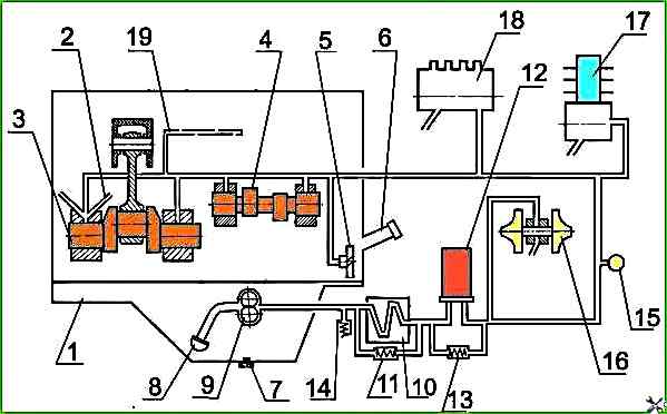
In case of excessive clogging of the filter paper, when the resistance of the oil filter becomes higher than 0.13-0.17 MPa, the bypass valve of the oil filter also opens, and the oil, bypassing the oil filter, enters the oil line.
When the diesel engine is running, it is strictly forbidden to unscrew the plug of the pressure-reducing valve.
From the main line of the diesel engine, oil flows through channels in the cylinder block to all main bearings of the crankshaft and journals of the camshaft.
From the main bearings, oil flows through channels in the crankshaft to all connecting rod bearings.
From the first main bearing, oil flows through special channels to the bushings of the intermediate gear and the gear of the fuel pump drive, as well as to fuel pump.
The valve train parts are lubricated with oil coming from the rear camshaft bearing through channels in the block, cylinder head, drilling in the IV rocker arm pillar into the inner cavity of the rocker arm shaft and through the hole to the rocker arm bushing, from which it goes through the channel to the adjusting screw and rod.
Oil comes to the compressor from the main line through drillings in the cylinder block and a special oil line.
From the compressor, the oil is drained into the diesel crankcase.
Oil comes to the turbocharger bearing unit through a tube connected to the outlet of the oil filter housing.
From the turbocharger bearing unit, the oil is discharged through a tube into the oil sump.
")

")
")
")
")
")
")
")