All seals and gaskets of the pump and its drive must be replaced during assembly.
The pump is assembled in the reverse order of disassembly.
After repair, the pump must be tested for performance on a special stand.
The pump must be assembled in conditions of complete cleanliness.
Before assembly, all used sealing parts and gaskets must be replaced, the parts must be washed and blown with dry compressed air.
During assembly, all mating surfaces of the pump parts must be lubricated with oil used for the hydraulic booster.

To assemble the pump, it must be installed on a special device (Fig. 1) so that the "Inlet" inscription is on the assembler's side.
The pump bushings are installed in pairs of the same size group.
In each size group, the bushings should not differ in height by more than 0.005 mm.
The driving and driven gears must also be of the same size group.
In each size group, the length of the teeth should not differ by more than 0.01 mm.
Before assembly, the bushings and gears must also be matched according to size groups.
The pump is assembled in the following sequence
In the wells of the housing insert two lower bushings of the same size group, then install the driven gear 4 (Fig. 2) and the driving gear 3, lubricated with oil up to half of the upper journal.
The driving gear is installed in the right well, and the driven gear - in the left.
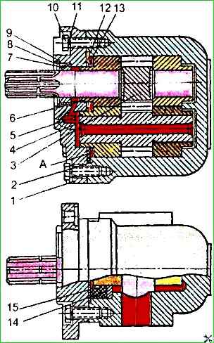
Insert the upper bushings into the wells of the housing until they contact the end surface of the gears, while normal contact is ensured by turning the bushings clockwise.
Install the insert 14 in the sector formed by two paired bushings until it contacts the end of the groove on the side of the hole marked "Inlet".
Install the special seal 15 in the sector of the pump housing with the cylindrical protrusion upward until it contacts the surface of the insert 14.
Then, using a special mandrel, install the cuff 12 with a recess at the top for the rings on the necks of the bushings.
Preliminarily, the inner cylindrical surfaces of the cuff must be lubricated with technical petroleum jelly or "Litol-24" grease.
Insert into groove of the cuff ring 13.
Install the cover 1 of the pump on the necks of the bushings, protecting the sealing surface of the cuff from damage.
The sealing edges protruding from the cuff must be directed inward into the pump body.
Protecting the splined end of the drive gear with a special cap, insert the cuff 8 into the pump cover, having previously lubricated it with oil.
After assembling the pump, the misalignment of the plane of the cover and the bushings should not exceed 0.1 mm.
After this, the pump must be installed in a special device, insert the guide sleeve into the hole in the cover, and the retaining ring 9 into the bushing.
Press the cuff into the cover until it stops and tighten the cover mounting bolts with the spring washers as an assembly.
Assembly of the pump drive and its installation on the engine is carried out in in the reverse order of disassembly.
Checking the power steering pump after assembly
The quality of the pump repair can be checked on a special stand equipped with control devices mod. KI-1774 or KI-4200.
Checking the power steering pump on the stand before installing it on the bus prevents repeated removal of the pump from the bus after repairs due to possible malfunctions.
Before checking, the pump must run at a speed of 1200 min -1 in the following mode:
- 2-3 min - at idle;
- 3-4 min - at a pressure of 2 MPa;
- 3-4 min - at a pressure of 4 MPa;
- 3-4 min - at a pressure of 6 MPa;
- 3-4 min - at a pressure of 8 MPa;
- 2-3 min - at a pressure of 10 MPa.
After running-in, the pumps are tested on a stand, during which the flow rate, volumetric efficiency and leakage of the working fluid through the drain of the pump shaft seal are determined.
The pump capacity at a rotation speed of 1200 min-1 and a pressure of 10 MPa must be at least 9.72 l/min.
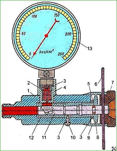
The volumetric efficiency of the pump at a temperature of 50 °C, a pressure of 10 MPa and a rotation speed of 1200 min-1 must be at least 0.9. It is permissible to check the pump after its installation on the bus using the throttle flow meter KI-1097 (see Fig. 3).
")

")
")
")
")
")
")
")