Figure 1 shows the D-245E3 engine control system.
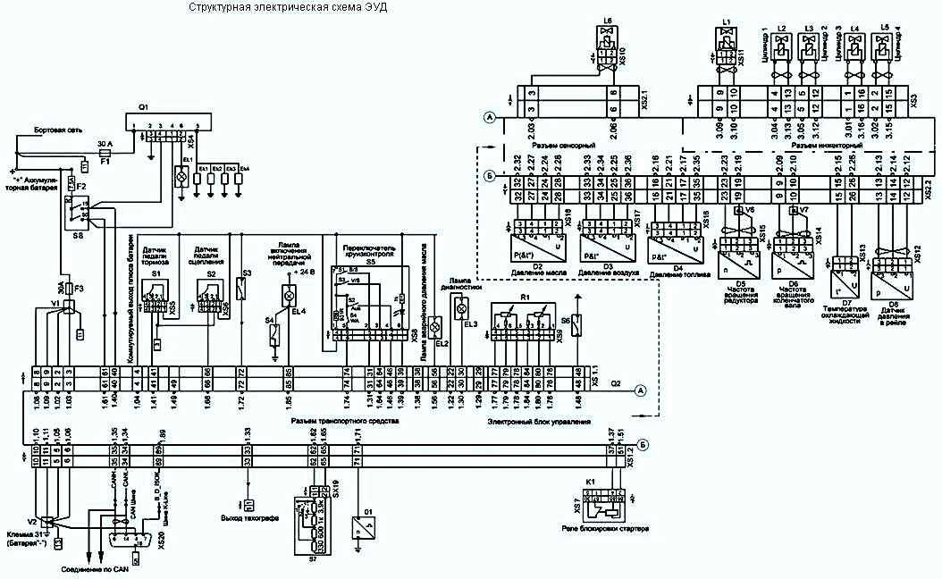
Explanations to the diagram are presented in Figures 2, 3, 4.

fig. 2

fig. 3

fig. 4
![]()
Figure 1 shows the D-245E3 engine control system.
Explanations to the diagram are presented in Figures 2, 3, 4.
fig. 2
fig. 3
fig. 4
Select your language
")

")
")
")
")
")
")
")