The front and rear suspension of the car are equipped with two hydraulic telescopic shock absorbers.
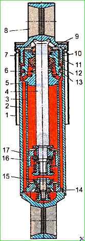
The design of the shock absorbers is shown in Figure 1, their main parameters are in the table.
If the rod, piston, working cylinder, valves are worn out or damaged, the shock absorber assembly must be replaced.
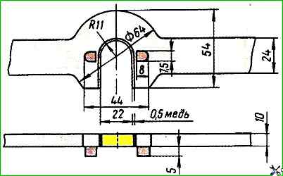
The holes in the brackets for the conical shock absorber mounting pin and the surface of the pin must be checked for paint with conical gauges.
The contact patch must occupy at least 75% of the cone surface.
Front suspension
Maximum length in a compressed state 416-410 mm
Diameter of the working cylinder 40.0-40.05 mm
Piston diameter 39.90-39.96 mm
Piston stroke, at least 231 mm
Outer diameter of the shock absorber casing 75 mm
Liquid volume 420-410 cm 3
Friction force, N, no more than 196
Rear suspension
Maximum length in compressed state 430-424 mm
Diameter of the working cylinder 40.0-40.05 mm
Piston diameter 39.90-39.96 mm
Piston stroke, not less than 245 mm
Outer diameter of the shock absorber casing 75 mm
Liquid volume 430-420 cm 3
Friction force, N, no more than 196
Mismatch The tolerance of the ends of the part and the caliber is allowed for the lower and upper brackets within 0.25 mm.
If a liquid leak occurs that is not eliminated by tightening the tank nut, the rod cuff must be replaced. To do this, remove the shock absorber from the vehicle, wash it in gasoline or kerosene, and blow it out with compressed air.
To disassemble the shock absorber, place it in a vice and secure it by the lower eye.

Pull the rod out of the reservoir 2 by the upper eye 8 (see Fig. 1) until it stops.
Use a special key to loosen the reservoir nut 10 (Fig. 2 and 3).
Remove from the working cylinder 3 (see Fig. 1) the rod with the eye 8 in assembly with the casing 1, piston, collars of the cuffs and the guide, having first lifted up the collar 7 by 30÷40 mm with the upper collar of the rod 9 and the collar of the nut of the reservoir 13 using a screwdriver.

Remove the working cylinder 3 together with the compression valve 14 from the reservoir 2.
Press out the compression valve 14 together from the working cylinder 3 (Fig. 1).
Remove the reservoir from the vice and drain the oil.
Install the rod together with the piston and the cuff clips in the vice and secure it by the eye.
Unscrew the rebound valve nut and remove the valve spring recoil.
Remove the recoil valve plate, washer, disc, throttle disc, piston with piston ring, bypass valve plate, valve spring and bypass valve limiting plate.
Remove rod guide 5 (see fig. 1) with a cuff 6, a spring, a washer, a collar 7 with a cuff 13, a rubber cuff of the rod 12 and a felt seal, a pressure washer, an upper cuff of the rod 9 with a collar, a nut gasket and a nut of the reservoir 10.
Remove the rod with an eye 8 from a vice.
Install the compression valve assembly in a vice and secure it by the head of the compression valve stem.
Unscrew the compression valve nut and remove the compression valve spring.
Remove the compression valve plate, the compression valve washer, the disk, the throttle disk, the compression valve body, the bypass valve plate, the spring and the limiting plate of the compression valve.
Remove the compression valve body from vice.
Wash the shock absorber parts with kerosene and blow them with compressed air.
It is not recommended to wash the parts with a soda solution or wipe them with cotton cloths.
")

")
")
")
")
")
")
")