To assemble the shock absorber, you need to:
Install the compression valve body in a vice and secure the compression valve stem.
Install the restrictor plate, spring, bypass valve plate, valve body, throttle disc, disc, washer, plate on the compression valve stem.
Install the compression valve spring, tighten the compression valve nut until it stops, and punch the valve stem at three points.
Remove the compression valve assembly from the vice.
Press the compression valve body into the working cylinder from the end side that does not have notches for air release.
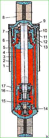
Install the rod with eye 8 (Fig. 1) in a vice, secure it by the eye and lubricate the rod with liquid AZh-12T TU 38.101432-75.
Install the reservoir nut 10, the cuff sleeve, the nut gasket, the upper rod sleeve, the cuff washer, the felt seal, the rubber sleeve 12, the sleeve 7 with the cuff 13, the washer, the spring guide 5 of the rod with the sealing ring 6 on the rod.

When installing seals 9 and 12, use a mandrel as shown in Figure 2.
Install the bypass valve limiting plate, spring, plate, piston with piston ring, compression valve throttle disc, rebound valve disc, washer and plate on the rod.
Install the compression valve spring, tighten the adjusting nut until it stops and punch the end of the rod at three points.
Remove the shock absorber rod assembly from the vice.
Install reservoir 2 in the vice and secure it by the eye
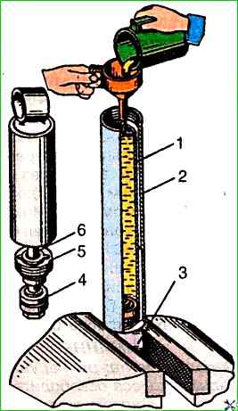
Install the working cylinder 3 in the reservoir together with the compression valve 14 and fill the working cylinder with the AZh12T TU 38101432-75 fluid in the amount specified in the table, as shown in Fig. 2.
It is also allowed to use MGP-10 fluid according to OST 38-1-54-74 or AU spindle oil according to OST 38 0141 2-87.
Install the rod assembly with the piston and the rod guide 5 into the working cylinder.
Tighten the reservoir nut 10 with a torque of 180-200 Nm.
When tightening the reservoir nut, the shock absorber rod must be in the extreme extended position.
The rod depth must be no more than 10 mm.
Lower the rod with the piston to the lower position. The piston should move freely, without jamming, along the entire length of the cylinder.
Remove the shock absorber assembly from the vice.
Shock absorber resistance forces
Compression stroke H:
Valve mode:
- Front suspension 1350±150;
- Rear suspension 1325±175
Throttle mode:
- Front suspension 575±75;
- Rear suspension 565±75
Recoil stroke H:
Valve mode:
- Front suspension 4000±500;
- Rear suspension 3350±450
Throttle mode:
- Front suspension 1275±175;
- Rear suspension 1400±200
To test the shock absorber, it must be installed on a test bench and secured.
Before recording the operating diagrams, the shock absorber must be bled (at least four cycles).
The shock absorber must be tested at the following strokes and piston movement frequencies:
At the valve mode: frequency - 100±2 cycles per min, piston stroke - 100±1 mm. The maximum piston speed is 0.52 m/s.
In throttle mode: frequency - 50 cycles per minute, piston stroke - 75±1 mm. In this case, the maximum piston travel speed is 0.2 m/s.
When testing on a bench, the resistance forces during the recoil stroke and compression stroke must correspond to the values in the table.
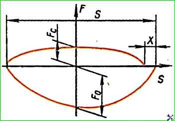
Working diagrams must correspond to the control diagram (Fig. 3), where Fc is the resistance force during the compression stroke; Fo is the resistance force during the rebound stroke; S is the piston travel. The absence of resistance forces is allowed in transition zone of the beginning of the compression stroke.
The permissible maximum value of free travel of the rod (X) should not exceed 0.1S.
The forces on the rod are controlled by the maximum points on the diagram, regardless of their location relative to the piston stroke.