The rod movement should begin when the air pressure in the above-diaphragm space is 0.005-0.010 MPa
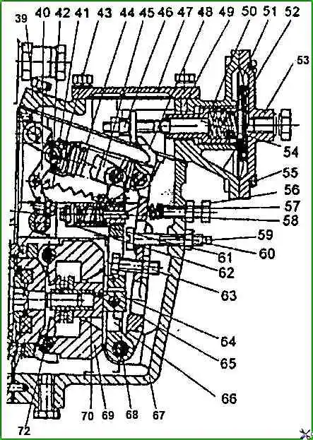
In the absence of pressure in the above-diaphragm space, the average cyclic feed is set by moving the stop 46 (see Fig. 1) and should be 60-70 mm 3 cycle at a pump camshaft speed of 550 min -1.
The adjustment of the start of movement of the diaphragm 51 (rod 54) must be done by changing the preliminary compression of the spring by screwing in or out the sleeve 50.
Movement of the sleeve 50 towards the diaphragm increases the air pressure corresponding to the start of the diaphragm operation; the movement of the sleeve from the diaphragm reduces the air pressure corresponding to the start of the diaphragm operation.
After adjusting the start of the diaphragm (rod) movement, install pin 49 in the hole in the corrector housing.
When installing the pin, ensure that its upper end does not protrude above the upper plane of the KPN housing, for which, if necessary, turn the corrector sleeve 50 in one direction or another by no more than 30°.
The pressure of the start of the diaphragm (rod) movement must remain within the established limits.
The pressure corresponding to the end of the KPN operation is determined by a series of successive measurements of the performance of the pump sections at the corresponding rotation frequency of the camshaft of the fuel pump.
The end of the KPN operation should be at a frequency of 550 min -1 and a pressure of 0.012-0.015 MPa.
Set the nominal speed of the pump camshaft to 1200 min -1, create a pressure in the above-diaphragm space of 0.06-0.065 MPa and make sure that the pump provides the nominal flow in accordance with the adjustment table
Install the union bolt, the corrector housing cover.