Before assembly, the spring sheets must be lubricated with graphite grease.
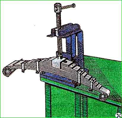
The springs are assembled in the device shown in Fig. 1.
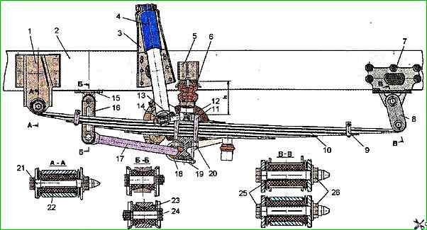
Front suspension: 1 - front bracket of the front spring; 2 - car frame; 3 - shock absorber mounting bracket; 4 - shock absorber; 5 - compression buffer bracket; 6 - compression buffer; 7 - rear bracket of the front spring; 8 - front spring clevis; 9 - spring clamp; 10 - spring; 11 - spring U-bolts; 12 - front spring lining; 13 - shock absorber mounting pin; 14 - washer; 15 - stabilizer mounting bracket; 16 - stabilizer clevis; 17 - stabilizer; 18 - stabilizer mounting cushion; 19 - rod mounting bracket; 20 - U-bolt mounting nuts; 21, 24, 25 - front spring-to-bracket mounting bolt; 22, 23 - spring mounting cushions; 26 - nut
When replacing rubber-metal hinges, they must be lubricated with a soap solution before installation.
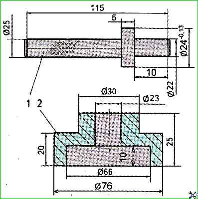
The sequence for installing rubber bushings is as follows: first, the spacer bushing 25 (see Fig. 2) is assembled with one of the bushings, then this bushing is pressed into the spring eye and after that the second bushing is installed on the other side.
Pressing the hinges into the spring eye using special mandrels (see Fig. 3).
Assembly of springs should be carried out in the following sequence:
Select a set of sheets;
Lubricate the surface of the sheets with graphite grease for springs without plastic gaskets or insert gaskets;
Insert into the hole under the center bolt installation mandrel with a diameter of 9 mm;
Compress the central part of the spring as close as possible to the mandrel and remove it;
Install the central bolt instead of the mandrel with the head towards the last short leaf of the spring and tighten the nut with a torque of 40 ÷ 50 Nm;
Install the clamps and tighten them with bolts and nuts.
The tightening torque of the nuts of the front and rear spring clamps should be within 40 ÷ 50 Nm;
Remove the spring from the device (vice, clamps, etc.) and remove excess grease from it.
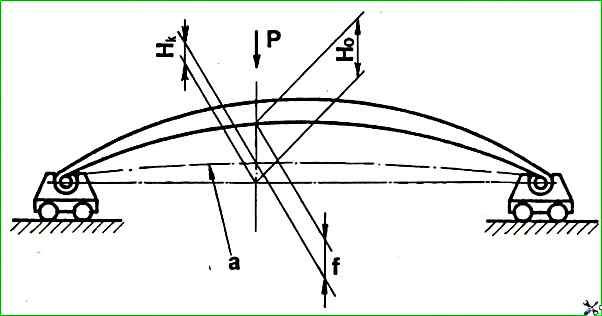
After assembly, the springs must be subjected to double subsidence with the load specified in the table and Fig. 4.
After this, it is necessary to measure the value of the control boom H, installing the spring on the press table and loading it with a load.
The value of the load and the deflection boom is determined depending on the model of the springs that are installed on a given car, depending on the year of manufacture.
The value of H is determined as follows.
Load the spring with a control load P and make the first measurement of the control boom H, then load the spring with an additional load of 3000-5000 H
And immediately remove it, leaving the control load P, make the second measurement of H.
From the two obtained values of the value H, obtain the arithmetic mean, which should not be lower than the values given in the table.
Front spring, five sheets of rectangular profile 75x9.5 or front, five sheets:
- Control load P kg H - 9500
- Bending arrow in free state H, mm - 247;
- Bending arrow under control load H kg mm - 42±6;
- Subsidence load P, H - 19500-27500
Front spring 1 and 5 sheets - rectangular profile 75x10 mm, 2, 3, 4 sheets T-shaped profile 75x11 mm:
- Control load P kg H - 10000
- Bending arrow in free state H, mm - 177;
- Bending arrow under control load H kg mm - 42±10;
- Load of settlement P, H - 24500-27000
Rear spring, 11 sheets of rectangular profile 75x10 mm, eye diameter 44 mm:
- Control load P kg H - 21000
- Arm deflection in free state H, mm - 157;
- Arm deflection under control load H kg mm - 32±6;
- Load of settlement P, H - 47000-27500
Rear spring, 11 sheets, 1, 2 and 11 sheets of rectangular profile 75x10 mm, 3-10 sheets of T-shaped profiles 75x12 mm, eye diameter 44 or 50 mm:
- Control load P kg H - 21000
- Barrel deflection in free state H, mm - 152;
- Barrel deflection under control load H kg mm - 22±10;
- Subsidence load P, H - 50000-60000
Subsidence and testing of front and rear springs should be performed on movable supports. The test scheme is shown in Fig. 4
After assembling and testing the front and rear springs, install them in place together with the shock absorbers on the vehicle in the reverse order of their dismantling.