The diesel air supply system includes an air filter and pipes connecting the filter to the turbocharger
Outside air enters directly into the air filter through the air intake pipe
Air filter
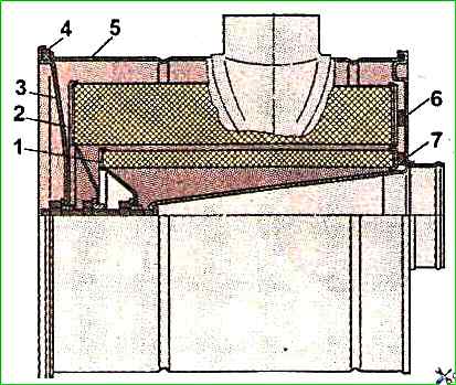
The dry-type air filter consists of a housing, two filter elements and a cover.
The filter is attached with clamps to a bracket installed in the engine compartment on the front panel of the cab.

The purpose of the small (internal) filter element is to ensure air purification in the event of mechanical destruction of the external filter element, which is why it is sometimes called the "safety element".
For normal operation of the diesel air supply system, it is necessary to monitor the tightness of the connections, preventing the suction of unpurified air into the diesel engine.
To facilitate monitoring of air filter clogging, a sensor is installed between the filter and the turbocharger, and an alarm is installed on the instrument panel.
As the filter becomes clogged, the vacuum in the intake manifold increases and when it reaches 4.5 kPa, the alarm is triggered.
When the alarm is triggered, the air filter should be serviced.
It is permissible to operate the car without the internal element
To service the filter, it is necessary to loosen the clamp of the connecting pipe.
Loosen bolts of the clamps securing the filter to the bracket, move them to the sides and remove the filter from the car or bus.
Unscrew the cover fastening nut, remove the cover, and then unscrew the nuts securing the filter elements and remove them from the filter housing.
If there is dust on the cardboard elements without soot or carbon (the element is gray), it is recommended to blow them with dry compressed air until the dust is completely removed.
To avoid rupture of the filter cardboard, the compressed air pressure should be no more than 0.2-0.3 MPa.
The air stream should be directed at an angle to the surface, the force of the stream should be adjusted by changing the distance between the hose tip and the element.
If there is dust, soot, oil, fuel on the cardboard that cannot be removed by blowing, you can wash the element in a solution of OP-7 or OP-10 detergent in warm water (40-50°C).
Solution composition: 20-25 g of substance per 1 l of water.
Instead of OP-7 or OP-10 solution, you can use a solution of the same concentration of washing powders "Novost", "Lotus", etc.
The element should be washed by immersing it for 30 minutes in the specified solution and rotating it vigorously.
After washing in the solution, rinse the element in clean water and dry thoroughly.
Before installing cleaned or new filter elements, it is necessary to visually check its condition by illuminating it from the inside with a lamp.
If there is mechanical damage to the cardboard, peeling of covers and casings and other defects, the elements should be replaced.
When a car or bus is operated for a long time in conditions of increased dustiness and with sudden changes in environmental conditions, it is recommended to determine the maintenance schedule based on experience in these conditions.
When assembling the air filter, pay attention to the condition of the sealing gaskets.
Gaskets with tears must be replaced.
The quality of the seal is controlled by the presence of a continuous imprint on the gasket.
When washing the car, do not allow water to enter the air filter to avoid hydraulic shock in the cylinders when starting the engine and on electrical equipment due to the possibility of damaging them.
If during operation the operating time between the necessary technical maintenance of the element two times in a row is less than 50 hours of diesel operation, the element must be replaced.
The estimated service life of the element is 1000 hours.
Turbocharger
The diesel engine is equipped with a turbocharger that uses the energy of the exhaust gases to supercharge air into the cylinders diesel.
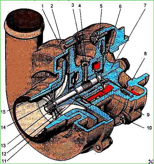
The turbocharger consists of a centrifugal single-stage compressor and a radial centripetal turbine.

The principle of operation of a turbocharger is that the exhaust y gases from the cylinders under pressure enter the chambers of the gas turbine through the exhaust manifold.
Expanding, the gases rotate the wheel of the centrifugal turbocharger.
The centrifugal turbocharger sucks in air through the air cleaner, compresses it and supplies it under pressure into the cylinders of the diesel engine.
The turbocharger bearing is lubricated with oil supplied through the pipeline from the centrifugal oil filter.
From the turbocharger, the oil drains into the diesel engine crankcase through the oil drain pipe.
Turbine wheel 7 is cast from heat-resistant nickel alloy and welded to the rotor shaft.
Compressor wheel 12 is cast from aluminum alloy and secured to the rotor shaft using a special nut 13.
In The turbocharger is equipped with contact gas-oil seals with spring rings 11.
On the turbine side, the sealing rings are installed in the groove of the sleeve 6, pressed onto the rotor shaft.
On the compressor side, the sealing rings are installed in the groove of the sleeve 14.
To increase the efficiency of the oil seal on the compressor side, the sealing ring area is separated from the area of active oil ejection from the bearing by an oil deflector 16, which forms an additional labyrinth.
The excess air pressure behind the compressor at the nominal operating mode of the diesel engine should be within 0.08-0.14 MPa.
During operation, the turbocharger does not require special maintenance.
The turbocharger must not be disassembled and repaired.
The condition of the turbocharger should be checked by the rotor runout time when stopped diesel.
To do this, after 3-5 minutes of operation at minimum idle speed, bring the diesel to maximum speed mode, then turn off the fuel supply.
The rotation of the turbocharger rotor after stopping the diesel engine should be heard for at least 5 s.
A smooth, constant-level sound with gradual attenuation indicates the normal condition of the turbocharger,
One of the reasons for a decrease in diesel power and increased smoking may be a decrease in boost pressure due to contamination of the flow part of the compressor, which can be determined by the tight rotation of the rotor.
If the rotor rotates tightly, then it is necessary to partially disassemble the turbocharger and flush the compressor part.
Before disassembling, thoroughly clean the outer surfaces of the turbocharger from dirt and dust.
To avoid damage to the blades when When disassembling and assembling the turbocharger, do not place the middle housing with the rotor on the compressor turbine wheel.
A special stand must be used for this purpose.
Partial disassembly, cleaning and assembly should be carried out in the following order:
- - unscrew the bolts securing housing 2 (see. fig. 2) of the compressor to the middle housing 5, and disconnect the compressor housing from the middle housing;
- - wash the compressor housing, the surface of the wheel and the middle housing with clean diesel fuel
- - connect the compressor housing to the middle housing, placing a paronite gasket between the flanges.
When installing the compressor housing, pay attention to the correct orientation of the compressor outlet pipe relative to the turbine housing flange;
- pour 10-15 g of clean motor oil into the oil channel of the middle housing and, pressing with your fingers on the ends of the rotor alternately on both sides, turn the rotor several times to check for smooth rotation and no jamming.


