ZIL-5301 vehicles are equipped with a combined pneumatic-hydraulic brake drive with two independent hydraulic and pneumatic circuits, divided into two circuits
AMO ZIL buses are equipped with a combined pneumatic-hydraulic brake drive with two independent hydraulic and pneumatic circuits and an ABS system.
ABS is also installed on ZIL-5301 vehicles upon customer request.
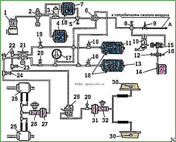
Fig. 1. ZIL-5301 brake drive diagram: 1 - compressor; 2 - pneumatic drive pressure regulator; 3 - moisture and oil separator; 4-regeneration cylinder; 5, 8, 12, 23, 24, and 29 - control output valves; 6 - triple safety valve, 7 - compensation cylinder; 9 - single safety valve; 10 - parking brake system valve; 11 and 13 - air cylinders; 14 - spring energy accumulator of the parking brake system drive; 15 - quick release valve; 16 - pneumatic-electric pressure drop sensors; 17 - two-needle pressure gauge of the service brake system; 18 - condensate drain valves from the air cylinders; 21 - two-section valve of the service brake system; 22 - brake signal switches; 25 - bracket with front axle brake hydraulic cylinders; 26 - front axle master brake cylinder; 27 - front axle pneumatic chamber; 28 - pneumatic drive brake force regulator; 30 - rear axle brake working hydraulic cylinders; 31 - rear axle wheel pneumatic chamber; 32 - rear axle master brake cylinder; A - to consumers
Blue line — compressed air preparation circuit;
yellow line — front axle brake drive circuit;
green line — rear axle brake drive circuit;
pink line — parking brake circuit;
red line — service brake hydraulic drive
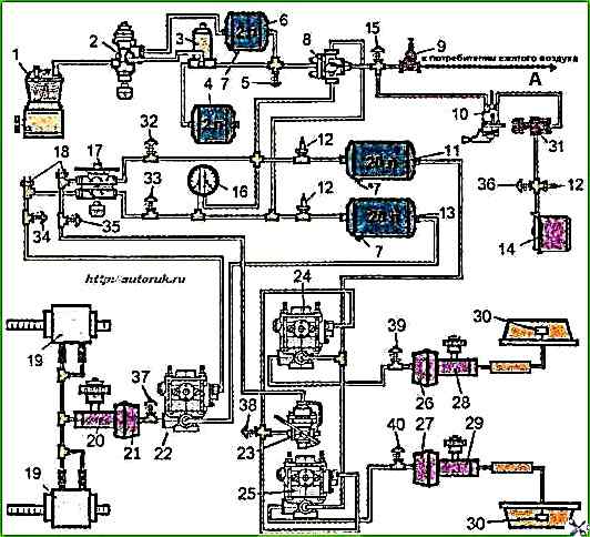
Fig. 2. Brake drive diagram of a bus and ZIL-5301 vehicles with ABS: 1 — compressor; 2 - pneumatic drive pressure regulator, 3 - moisture and oil separator, 4 - regeneration cylinder; 5, 15, 32, 33, 34,35,36,37,38,39 and 40 - control outlet valves, 6 - compensation cylinder, 7 - condensate return taps; 8 - triple safety valve, 9 - single safety valve, 10 - parking brake system tap; 11 and 13 - air cylinders, 12 - pneumatic-electric pressure drop sensors, 14 - spring energy accumulator of the parking brake system drive; 16 - two-needle pressure gauge of the service brake system, 17 - two-section valve of the service brake system, 18 - brake signal switches, 19 - bracket with front axle brake hydraulic cylinders, 20 - front axle master cylinder, 21 - front axle air chamber, 22 - front axle modulator; 23 - brake force regulator, 24 - rear axle right wheel modulator; 25 - rear axle left wheel modulator, 26 - rear axle right wheel air chamber; 27 - rear axle right wheel air chamber, 28 - rear axle right wheel master cylinder, 29 - rear axle left wheel master cylinder; 30 - rear axle brake working hydraulic cylinders, 31 - quick release valve; A - to consumers
")

")
")
")
")
")
")
")