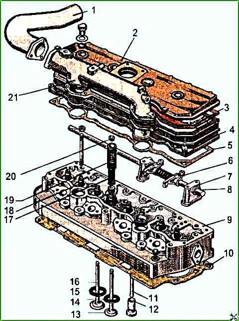
Installing the cylinder head and valve mechanism D-245
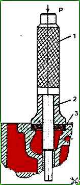
If it is necessary to replace the valve seats, use a set of special mandrels shown in the figures
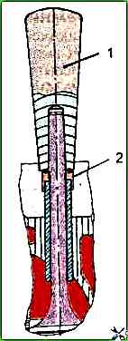
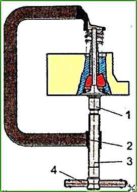
It is recommended to install the valve springs and valve cuffs using a special device and mandrel shown in the figures
The cylinder head gaskets must be lubricated on both sides with graphite paste consisting of 60% engine oil and 40% graphite (by weight).
Fluoroplastic rings must be put on the metal edging of the holes for the liners.
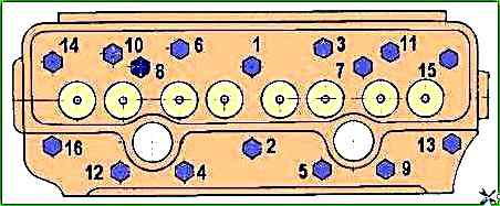
Tightening of the bolts (nuts) for fastening the head must be carried out in the sequence shown in Fig. 3.
Tightening torque - 190-210 Nm.
The pushrods should be installed in the cylinder head holes so that the pushrod tips fit into the pushrod recesses.
When installing the valve mechanism, the adjusting screw spheres should be aligned with the pushrod tips.
The stud nuts and valve mechanism mounting bolts must be tightened to the stop.
The gap between the rocker arm striker and the end of the valve stem on an unheated diesel engine should be: intake valves - 0.2 +0.05 mm; exhaust valves - 0.45-0.05 mm.
Adjustment should be made in the following sequence:
- - turn the crankshaft until the valves overlap in the first cylinder (the intake valve of the first cylinder begins to open, and the exhaust valve finishes closing) and adjust the clearances in the fourth, sixth, seventh and eighth valves (counting from the fan);
- - then turn the crankshaft one revolution, setting the overlap in the fourth cylinder, and adjust the clearances in the first, second, third and fifth valves.
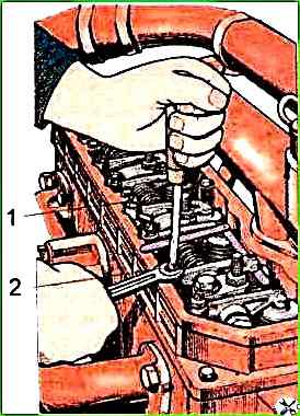
To adjust the clearance, loosen the lock nut of the screw on the rocker arm of the adjustable valve and, turning the screw, set the required clearance using the feeler gauge between the rocker striker and the end of the valve stem.
After setting the clearance, tighten the lock nut. After adjusting the valve clearance, install the cylinder head cover cap.
Check the tightening of the cylinder head mounting bolts after running-in and every 40 thousand. km of mileage on a warmed-up diesel engine.
Check the clearances between the valves and rocker arms and, if necessary, adjust them every 20 thousand km of mileage, as well as after removing the cylinder head, tightening the cylinder head mounting bolts and when valve knocking occurs.
Valve clearances should be checked at a temperature of no more than 60°C.
")

")
")
")
")
")
")
")