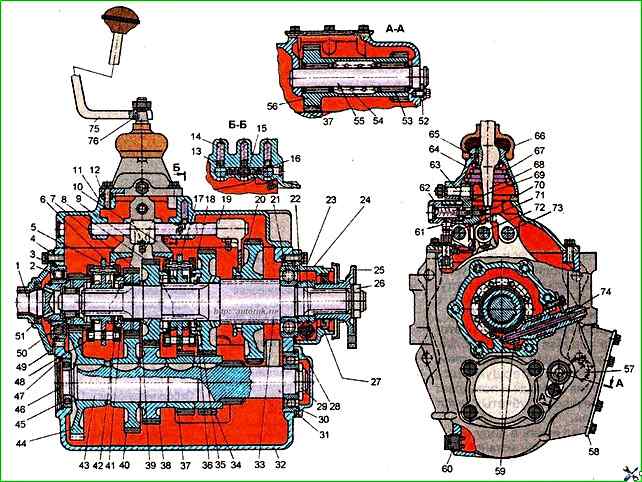
ZIL vehicles and their modifications are equipped with a mechanical, five-speed gearbox with synchronizers (Fig. 1).

Gearbox: 1 - input shaft: 2, 21, 30 and 45 - bearings: 3, 28, 31 and 47 - retaining rings; 4 - cover of the rear bearing of the input shaft: 5 - synchronizer for fourth and fifth gears; 6 - fourth gear bushing; 7 and 40 - gear pair of fourth gear; 8 and 38 - gear pair of third gear: 9 - head of the shift rod for first gear and reverse gear': 10 - fork for shifting second and third gears; 11 - gearbox cover: 12 - installation sleeve; 13 - latch ball: 14 - latch spring; 15 - pin of the locking device of the gear shift rods: 16 • ball of the locking device: 17 - synchronizer for the second and third gears: 18 and 34 - gear pair of the second gear: 19 - fork for shifting the first gear and reverse gear; 20 • gear wheel of first gear and reverse gear; 22 - speedometer drive worm; 23 and 59 - speedometer drive gears: 24 - secondary shaft bearing cover; 25 - flange with reflector; 26 - secondary shaft flange nut; 27 and 51 - cuffs; 29 - intermediate shaft nut; 32 - gearbox housing; 33 - secondary shaft; 35, 39 and 41 support washers; 36 and 42 - locking rings; 37 - gear wheel for reverse gear of the intermediate shaft; 43 - intermediate shaft; 44 - constant mesh gear: 46 - plug; 48 - gasket; 49 • locking pin: 50 and 53 - roller bearings: 52 - locking plate; 54 and 67 - springs; 55 - axis of the gear wheel block for reverse gear; 56 - block of gear wheels for reverse gear; 57 - control filler plug; 58 - power take-off hatch cover: 60 - drain plug with magnet; 61 - breather: 62 - fuse for turning off the first a. gears and reverse gears; 63 - axis of the intermediate lever; 64 - housing for the tip of the 1st gear shift lever: 65 - lever retainer: 66 - gear shift lever cover; 68 - tip of the gear shift lever: 69 • intermediate lever; 70 - intermediate lever block; 71 - shift rod for first gear 5 and reverse gear; 72 - shift rod for fourth and fifth gears; 73 - shift rod for second and third gears: 74 - speedometer drive shaft fitting; 75 - gear shift lever; 76 – key

The use of synchronizers in the gearbox makes driving easier, ensures quiet gear shifting and increases the durability of gear couplings.

It should be borne in mind that the gearboxes are equipped with a worm 22 and a gear 59 for the speedometer drive, designed for a specific gear ratio in the rear axle.

Gearbox type: mechanical with five gears for moving forward and one in reverse

Gear ratios:

  • - first gear 6.45
  • - second gear 3.56
  • - third gear 1.98
  • - fourth gear 1.275.
  • - fifth gear 1.00 (direct)
  • - reverse gear 6.15

Maximum torque transmitted to the gearbox, N.m 410

Gear shifting is mechanical, with a rocker lever mounted on the box cover

Power take-off. From the reverse gear block

Maximum power of the power take-off, kW (hp) 22.08 (30)

Possible gearbox malfunctions

Cause of malfunction - Elimination method

Difficulty engaging all gears, reverse gear and first gear engage with a grinding noise

Incomplete disengagement of the clutch (the clutch “leads”) - Adjust the free play of the clutch release bearing coupling

Shifting gears with a bang and a grinding noise

Wear of synchronizer cone rings or locking chamfers of pins and carriage - Replace synchronizers

Self-switching gears on the go

Incomplete gear engagement due to a malfunction of the shift mechanism, wear of the fork grooves or loosening of the forks and levers - Eliminate malfunctions, replace worn parts

Gears are not included

Destruction of driven shaft gear bearings, breakage of pins or synchronizer clamps - Replace faulty parts - Replace synchronizers

Increased noise level during gearbox operation

Wear or breakage of gear teeth. Bearing failure - Replace faulty parts.

Oil leak from gearbox

Cuff wear or loss of elasticity

Increased pressure in the gearbox crankcase, leakage on sealing surfaces - Replace cuffs

Rinse the breather. Tighten fasteners, replace gaskets

new

Adjust the bearings carefully. If the bearings are loosely tightened during movement, impacts occur that destroy the bearings.

The tanks are attached to the frame side members from the outside using brackets and clamps. Cardboard spacers are placed between the clamps and the tank