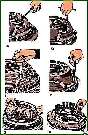
Assembly of the pressure plate should be carried out in the reverse order of disassembly, on an auxiliary flywheel used as a device, placing a steel disk with a diameter of 300 mm and a thickness of 9.8 mm under the clutch pressure plate to adjust the position of the levers
Install the flywheel on a mechanic's workbench, put a steel disk on it and install the clutch pressure plate on it (see Fig. 1).
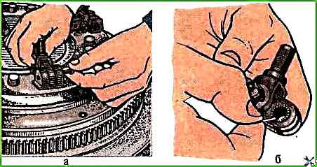
Assemble the needle bearings by inserting a soft oil-resistant rubber technological ball with a diameter of 8.8-9.5 mm into the lever hole
Then insert nineteen needle rollers lubricated with Litol-24 grease between the rubber ball and the wall of the lever hole.
In the same way, insert nineteen needle rollers into the second hole of the lever.
Align the hole of the support fork with the hole of the lever; in this case, the spherical protrusion of the inner end of the lever should be directed in the same direction as the threaded rod at the fork.
Insert the short pin into the aligned holes, pushing out the rubber ball.
Cotter pin the pin.
Observing the markings made during disassembly, install the lever in the groove between the lugs of the pressure plate, aligning the holes in the lever and lugs.
Insert the long pin (see Fig. 2a) into the aligned holes, pushing out the rubber ball.
Cotter pin the pin.
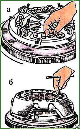
If there are no rubber balls, the needle rollers can be assembled by applying a layer of grease to the surface of the holes, to which the rollers are glued.
Moreover, the needle rollers should be placed in the second hole after assembling the lever with the fork (see Fig. 2b).
Install the remaining levers in a similar manner. In this case, the heads of the fingers should be in the direction of rotation.
Place heat-insulating washers on the protrusions of the pressure plate (Fig. 3a), and place pressure springs on the washers (see Fig. 1e).
Having aligned the marks on the casing and the disk, made during disassembly to maintain balance, install the clutch casing on the springs (see Fig. 1d), directing them towards the protrusions on the inner surface of the casing; in this case, the threaded ends of the support forks should enter the holes in the casing.
To prevent the threaded rods of the lever forks from jumping out of the casing holes, it is advisable to put extensions in the form of thin-walled tubes on them.
Align the holes on the support legs of the casing with the threaded holes of the auxiliary flywheel, install the extended centering bolts and pull the casing legs to the flywheel, gradually and sequentially tightening all the bolts.
Install the bushings in the shaped holes of the paired tangential spring plates, screw in the fastening bolts of these plates, tighten the bolts (the tightening torque should be 10-15 Nm)
Then lock them by bending the thin flange of the bushing onto the edge of the bolt head.
Screw the adjusting nuts onto the threaded rods of the forks until the end faces match nuts with the end of the threaded rod of the fork.
Install the support pressure plates and lock plates on the adjusting nuts, screw in the bolts for fastening these plates and tighten them preliminarily until the ends of the support plates touch the casing.
Adjusting the clutch release levers
Without removing the assembled clutch pressure plate from the auxiliary flywheel used as a device, it is necessary to adjust the position of the ends of the levers relative to the working surface of the pressure plate.
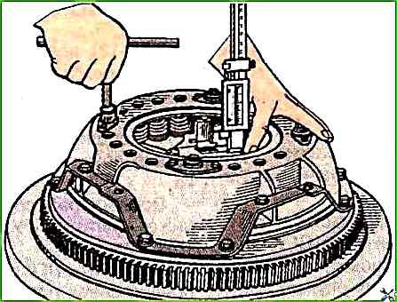
Turning the adjusting nuts with a wrench (Fig. 4), set all the levers in such a position that the distance from the working surface of the pressure plate to the tops of the spherical protrusions on the inner ends of the levers is within 39.7-40.7 mm
In this case, the ends of the levers should lie in the same plane, parallel to the working surface of the pressure plate with an accuracy of 0.5 mm.
Measurements should be made using a height gauge ШР-250 GOST 164-73, resting it on a steel disk replacing the driven disk. Fig. 4
Adjusting and checking the location of the clutch release levers using a disk and a height gauge
After adjusting the clutch, tighten the support plate mounting bolts (tightening torque 10-15 Nm)
Lock the bolts by bending one antenna of the locking plate along the edge of the bolt and lock the threaded connection of the adjusting nut with the threaded end of the fork (punch at one point).
Unscrew the casing mounting bolts to the auxiliary flywheel and remove the disk assembled with the casing.
In this case, all bolts should be unscrewed gradually and sequentially to avoid deformation of the clutch casing.
Installing the clutch on the engine
Install the driven disk, directing the protruding part of the disk hub towards the flywheel, install the pressure plate assembly with the casing on the flywheel, aligning the existing marks on the casing and flywheel, secure the casing on the flywheel, having first tightened several mounting bolts by hand.
Center the driven disk relative to the flywheel with a special splined mandrel or an auxiliary primary shaft of the gearbox, inserting it into the splined hole of the hub of the driven disk and into the bearing of the crankshaft flange.
Tighten the missing mounting bolts and finally tighten the casing to the flywheel, having first placed spring washers under the heads of the bolts washers.
Tighten all bolts gradually and consistently with a torque of 28-36 Nm.
Remove the auxiliary shaft from the splined hole.
Install the clutch release fork, fork flange and secure it with bolts and spring washers.
Then put the fork lever on the small splines, aligning the marks on the lever and the end of the fork, insert and tighten the lever lock screw with a spring washer.
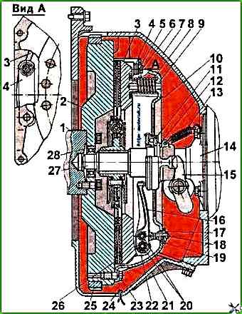
Some mechanics, due to inexperience, install the driven disk the wrong way, although in principle it can be installed the wrong way. But in this case, the disk will quickly fail.
Look at the cross-section and install it as in the picture.
")

")
")
")
")
")
")
")