Before assembly, wash the main gear and differential parts in the cleaning solution MS 6, MS 8 TU 6-15-978-76, blow with compressed air, check for compliance with technical requirements
It is recommended to lubricate the joint planes and sealing gaskets with UG-6 paste.
The final drive gear installed in the crankcase should rotate smoothly, without jamming.
The drain and filler plugs, as well as bolts with an entrance to the cavities with oil, must be installed on UG-6 or UN-25 pastes.
The main gear pinions are selected in pairs at the factory, each pinion is assigned a kit number.
If one pinion is faulty, both should be replaced.
Assembling the shaft of the driving bevel gear
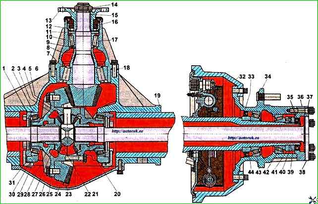
Press the outer ring of the front bearing 17 into the cup 10 (see Fig. 1) of the bearings of the driving bevel gear until it stops against the flange using a mandrel (interference 0009…0059 mm).
Turn the cup and press in the outer ring of the rear bearing 7 of the shaft (interference 010...0.068 mm).
Press the inner ring of the rear roller bearing 7 onto the shaft of the driving pinion 15.
Put the spacer onto the shaft of the driving pinion 15 bushing 8, adjusting washers 9, if no parts were changed, and the bearing clearance was determined before disassembly, the thickness of the newly installed washers should be less by the clearance value, rounded up to tenths of a millimeter.
Install front bearing 17.
Install thrust washer 11, technological flange 13 (without mud deflector) on the shaft splines and press it on.
Put on the nut washer and secure the flange with nut 14 (lock the nut only after checking the bearing preload).
Assembling the differential
The differential cups must have the same serial number of the set and marks, which should be aligned when assembly.
The gears and differential cups should be lubricated with engine oil during assembly.
Install the right differential cup on the plate, place the bearing on the chamfer of the cup neck and press it on using a mandrel (bearing tension is 0.020-0.055 mm).
The sequence of operations for assembling the left differential cup is the same as for the right one.
Install the left differential cup on a support with a hole in which the neck with the bearing should be placed.
Install the thrust washer and the gear of the left half-shaft into the cup.
Insert the pin of the satellite into the hole of the differential cup to a depth of about 5 mm, aligning the axis of the hole in the pin parallel to the axis of the hole for the pin in the differential cup, and press in with light hammer blows until the pin appears from the hole by about 5 mm.
Put the pin, thrust washer and satellite on it and, holding them by hand, press the pin until the holes for the pin align.
Press the pin with a special mandrel to a depth of 17.05-18.05 mm.
Install the crosspiece housing and the opposite satellite with the thrust washer into the cup on the pin.
Press the second pin in the manner described above, and then the two remaining ones.
Place the right half-shaft gear with the thrust washer on the satellites, install the right differential cup, aligning the cups according to the marks made with a center punch during disassembly, and tighten the bolts by hand, installing the locking plates on them in pairs.
Remove the differential from the stand and install it in a vice. Tighten the bolts evenly.
The bolt tightening torque is 100-120 Nm. Bend the locking plates onto the edge of each bolt.
Install the driven gear on the differential and secure it with bolts and locking plates. The bolt tightening torque is 160-200 Nm.
The engagement of the differential gears and their rotation in the assembled differential must be free when turned by hand.
The permissible runout of the driven gear torus during installation. on the bearing journals of the assembled differential must not exceed 0,12 mm.
Assembling the main gear
Install the cup of the leading bevel gear in assembly with bearings and adjusting shims into the rear axle housing.
The set of adjusting shims produced by the plant consists of five standard sizes with a thickness of 1.0; 0.5; 0.2; 0.1 and 0.05 mm.
During assembly, the engagement of the teeth of the bevel gears and the adjustment of the differential bearings are simultaneously performed.
The number of shims is selected empirically, focusing on the shape of the contact patch in the engagement. Initially, install the previously installed kit.
There must be at least two 0.05 mm thick gaskets under the cup flange, and at least one 0.1 mm thick gasket, and the rest as needed, with thin gaskets installed on both sides of the gasket set.
Before installation, the steel adjusting gaskets must be lubricated with AU spindle oil or I-30 industrial oil.
The drive gear bearing cup mounting bolts must be finally tightened to a torque of 70-100 Nm, while the drive gear must rotate smoothly, without jamming.
Install the differential in the crankcase on the bearing seats.
Tighten the adjusting nuts by hand and install the bearing caps.
To avoid damaging the threads on the crankcase, caps and nuts, when installing the caps, ensure that matching of threads on mating parts.
The bearing cap fastening bolts must be tightened with a torque of 160-200 Nm.
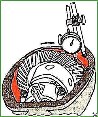
The gap is measured with an indicator installed on the wide part of the tooth (Fig. 2).
Adjust the tension of the differential bearings and the engagement of the gears along the contact patch, as described in the article - "Adjusting the main gear".
Installing brakes and hubs on the rear axle wheels.
The outer bearing rings are not interchangeable, so if necessary, each bearing is replaced as a set.
Install the wheel hub and adjust the clearance in the wheel bearings.
Adjust as follows:
- 1. Tighten the adjusting nut to a torque of 60..80 Nm, turning the hub in both directions to correctly install the rollers in the bearings. Axial clearance is not allowed, the hub should not rotate after tightening;
- 2. unscrew the adjusting nut by approximately 45°. Install the lock washer.
If the hole in the lock washer does not match the pin on the adjusting nut, you can try turning the washer 180°, a slight turn of the nut in either direction is also allowed;
- 3. Tighten the lock nut to a torque of 250-300 Nm. During operation, if the axial clearance is checked with an indicator head, the clearance should be within 0.125-0.25 mm.
The correctness of the adjustment is checked by heating the hubs after a run of 8-10 km. Slight heating of the hubs is allowed only for new bearings.
In case of significant heating, the adjustment should be repeated. Do not use the brakes when checking, because they can cause significant heating.
The axle marking is made at the factory by impact on the rear part of the right axle housing casing and contains information about the gear ratio of the main gear, the date of manufacture and the catalog number of the axle assembly.
Installing the axle shafts
Install the seal housing together with the seal and the axle shaft gasket onto the axle studs. Insert the axle shafts with the splined end into the axle gears of the differential.
Put the axle shaft flanges onto the wheel hub studs. Place expansion bushings and spring washers on studs, screw on nuts and tighten them to 70-90 Nm.
The rear axle is installed on the bus in the reverse order of disassembly.
Testing the drive axle
The assembled rear axle must be tested on a stand or by running on a vehicle. The tested axles must meet the following requirements (at the end of the tests):
- 1. No pronounced noise from the main gear gears, as well as knocks and sharply distinguishable noise in the differential with one braked drum are allowed;
- 2. The installation locations of the drive gear and differential bearings in the crankcase and crankcase cover, as well as the installation locations of the wheel hub bearings must be cold or warm, but not more than 50°C; heating of the brake drum is also allowed to be no more than 50°C (checking can be done by hand by touch);
- 3. There should be no oil leakage through the cuffs and in the connections.
")

")
")
")
")
")
")
")