Removal and disassembly of the ZIL-5301 diesel engine
To dismantle the power unit, it is recommended to install the bus on an inspection pit, above which there is a lifting device
The mass of the power unit assembly without refueling and oil is 600 kg, therefore, to dismantle it, it is necessary to have a lifting device with a lifting capacity of at least 1 t; the height to the hook must be at least 2 m.
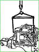
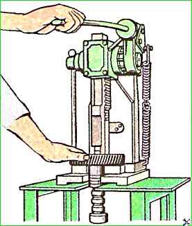
Dismantling a diesel engine from a car or bus using a lifting device is shown in Fig. 1
Before dismantling the power unit from a car or bus, it is necessary to drain the coolant from the cooling system, and also drain the oil from the diesel engine crankcase and gearbox.
The coolant is drained through two drain cocks.
When disassembling, it is recommended to place small parts in a separate container, and when disconnecting wires from electrical equipment, install screws and nuts in their original position and tighten by hand.
Before dismantling the power unit, the following preparatory work must be performed:
- - remove the battery compartment hatch cover and disconnect the wires from the positive battery pole, remove the starter wire, disconnect the ground with a switch;
- - lift hood of a car or bus and disconnect the wires from the instruments and adapter blocks, loosening the screws of the clamping clamps, disconnect the hoses of the liquid and oil radiators and the tube with hoses going to the heater;
- - disconnect the blind drive cable (if any) and remove it together with the casing from the opening in the front wall of the cabin;
- - dismantle the plumage;
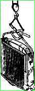
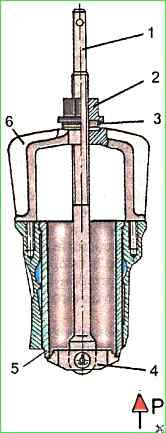
- - unscrew the radiator mounting nuts and remove it manually or using the KZ-0355 device (Fig. 2);
- - remove the rubber cushions with the spacer sleeve;
- - disconnect the high-pressure fuel pump (HPFP) drive, remove the foot drive rod, the manual fuel shut-off cable;
- - disconnect and remove the tubes: draining compressed air from the compressor, pressure regulator, supplying fuel to the fuel pump;
- - disconnect the high and low pressure hoses from the power steering pump housing;
- - remove the steering cardan shaft;
- - disconnect the muffler inlet pipe from the exhaust pipe by unscrewing nuts;
- - disconnect the pipe going from the air filter to the turbocharger;
- - remove the cabin floor hatch cover by unscrewing the mounting bolts; remove the gearbox lever housing with the gasket together with the lever by unscrewing the housing mounting bolts.
Cover the hole for the gearbox housing with a cardboard cover, securing it with two bolts
- - disconnect the speedometer drive by unscrewing the union nut and the tachometer drive;
- - disconnect the service brake pedal drive by disconnecting the rod and pedal lever;
- - disconnect the propeller shaft from the gearbox flange by unscrewing the mounting nuts;
- - disconnect the clutch release drive by disconnecting the pipelines on the pneumatic hydraulic booster (PGU), having first drained the fluid from the drive;
- - unscrew the bolts securing the front support and two rear supports of the diesel engine. Disconnect the brake pipes from the parking brake system valve (when installing the parking brake drive from the energy accumulator).
Unscrew the bolts securing the bumper and the front cross member of the frame and remove them from the car or bus.
Carefully lifting the power unit by the eyebolts with a lifting device (see Fig. 1), remove it from the frame of the car or bus under the engine cross member, unscrewing the bolts of its fastening, and, moving the power unit forward, remove it from the car or bus.
Then install the power unit on a special trolley for transportation to the disassembly site.
Dismantling instruments and external units from a diesel engine
Before disassembling, the diesel engine must be cleaned of dirt and oil, washed with kerosene or a degreasing solution.
It is recommended to use cleaning solutions for washing MS-6 or MS-8 TU 6-15-978-76 with a concentration of 20-30 g/l at a temperature of 90-100 °C.
Then blow out the diesel with compressed air.
It is recommended to remove instruments and units from the diesel on a stationary rotary stand mod. OPR-989.
The gearbox must be removed from the diesel before installing the diesel to the stand.
The diesel engine rotates around the horizontal axis of the stand using a worm gear located on the stand.
When disassembling or assembling, the diesel engine must be fixed in any position when the worm gear is braking.
During disassembling the diesel engine, all parts suitable for further operation must be protected from damage.
The parts and standard parts removed from the diesel engine must be placed in a specially prepared container in which they are transported for washing, checking and troubleshooting operations.
Most diesel engine parts are interchangeable, but some require individual adjustment with the mating part.
When dismantling the gearbox, it is necessary to:
- - unscrew the gearbox mounting nuts with an open-end wrench;
- - disconnect the PGU rod by removing the pin from the clutch fork lever;
- - disconnect the box from the clutch housing using a mounting blade and, while rocking it, remove it with a hoist or using a hydraulic lift. In this case, pay attention to the position of the clutch release fork.
To dismantle the clutch housing, remove the clutch housing cover, unscrew the bolts securing the housing to the rear sheet and remove it from the mounting pins.
To dismantle the clutch, use an end wrench to unscrew the bolts securing the clutch housing, remove the pressure plate assembly with the housing and clutch release lever, and remove the driven disk assembly.
When removing the oil filter, you must:
- - unscrew the bolts securing the filter housing;
- - remove the filter from the diesel engine together with the sealing gasket,
When dismantling the starter, you must:
- - unscrew the bolts and nuts securing the starter to the clutch housing;
- - remove the starter from the socket crankcase,
To remove the generator, you should:
- - unscrew the tension bar mounting bolt;
- - unscrew the nuts securing the generator to the bracket;
- - remove the generator and generator drive belts, releasing the generator pulley from the drive belts.
After this, you need to remove the generator brackets from the diesel engine by unscrewing the bolts securing them.
When dismantling the fan and liquid pump, you need to do the following:
- - unscrew the bolts securing the fan to the pulley;
- - remove the fan;
- - unscrew the bolts securing the liquid pump housing to the end of the block;
- - remove the pump with gaskets.
Diesel Disassembly D-245
The diesel engine is disassembled in the following sequence.
With the diesel engine installed on the stand with the sump down, remove the thermostat with the branch pipe, the liquid pump housing and the fan assembly.
Then, unscrew the exhaust manifold mounting nuts and remove it.
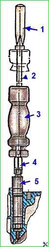
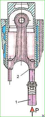
Using the inertial universal puller kit, remove the injectors from the diesel engine (Fig. 1).
Remove the cap and cover from the valve mechanism, the oil supply pipe to the rocker shaft.
Remove the axle struts assembled with the rocker shaft and the rocker arms themselves and remove the rods from the cylinder block.
Unscrew the cylinder head mounting bolts, remove the cylinder head and gasket.
Unscrew the bolt securing the liquid pump and fan drive pulley from the end of the crankshaft, remove the front diesel support, and then the pulley using a special puller.
Remove the timing gear cover, the intermediate gear and unscrew the two bolts securing the thrust flange, and then, turning the camshaft, remove it from the cylinder block.
Remove the camshaft drive gear using a press and a mandrel, after unscrewing the gear mounting bolt.
Remove the flywheel, seal housing with rubber cuff, oil deflector washer and rear sheet of the diesel engine.
Turn the diesel engine 90 and remove the oil pan and connecting rod caps with liners; remove the connecting rods from the cylinders together with the pistons and put the connecting rod caps back in place.
When disassembling a diesel engine, the pistons with connecting rods should be removed only upwards. Before removing the pistons, remove carbon deposits from the upper part of the cylinder liner.
When replacing parts of the piston-liner group and the crank mechanism, pay special attention to the size groups of the parts.
Unscrew the nuts securing the main bearing caps and remove them together with the liners.
Remove the crankshaft and remove the tappets.
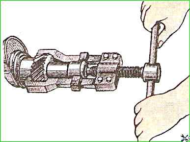
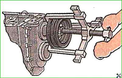
Gears can be removed from the crankshaft using the universal puller 1P-21305 (Fig. 5).
Remove the compression and oil scraper rings from the pistons using the I804.03.000 tool (Fig. 6).
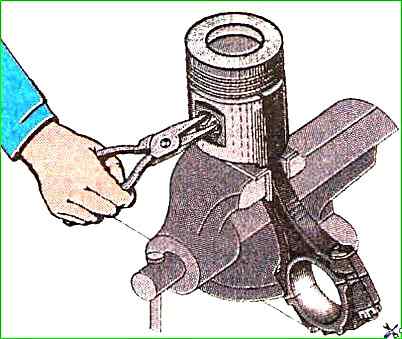
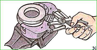
Remove the retaining rings from the piston bosses using round-nose pliers (Fig. 7); press out the piston pins
Press out the cylinder liners from the block using the I804.01.000 device (Fig. 8).
After disassembling, all diesel parts must be washed and blown with compressed air.
For washing, use MS-6 or MS-8 TU 6-15-978-76 cleaning solutions with a concentration of 20 - 30 g/l at a temperature of 90-100°.
")

")
")
")
")
")
")
")