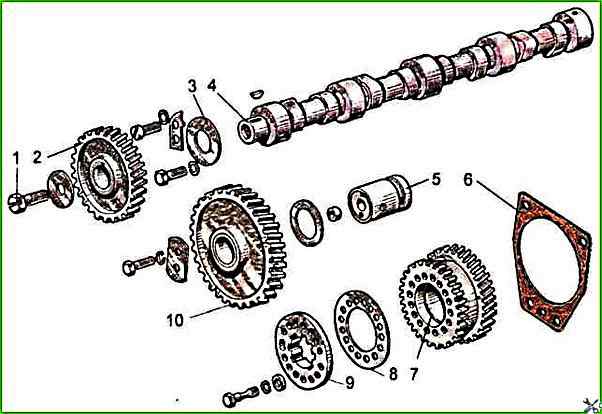
Requirements for the ZIL-5301 timing mechanism parts
The timing mechanism consists of a camshaft, intake and exhaust valves, as well as parts for their installation and drive: tappets, rods, rocker arms, adjusting screws with nuts, plates with crackers, springs, struts and rocker arm shafts
The tappets are steel and have spherical bottoms.
Due to the fact that the camshaft cams are made with a slight inclination, the tappets perform a rotational motion during operation.
The tappet rods are made of steel rod.
The spherical part entering the tappet and the cup of the rod are hardened.
Valve rocker arms - steel, swing on an axis mounted on four struts. The outer struts are of increased rigidity.
Rocker arm axis - hollow; has eight radial holes for lubricating the rocker arms.
The movement of the rocker arms along the axis is limited by spacer springs.
The intake and exhaust valves are made of heat-resistant steel.
They move in guide bushings pressed into the cylinder head.
Each valve closes under the action of two springs, outer and inner, which act on the valve through the plate and crackers.
Sealing cuffs installed on the valve guide bushings prevent oil from entering the diesel cylinders through the gaps between the valve stems and guide bushings.
The working surfaces of the bearing journals and camshaft cams must be clean, without nicks and scratches.
The height of the camshaft cams must be equal to 41.32 ± 0.05 mm.
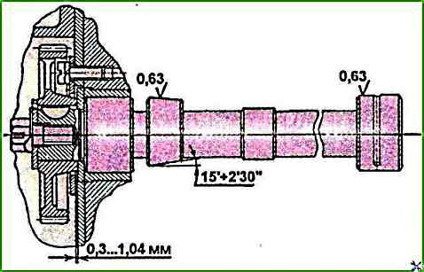
The cam surfaces must be machined to a cone (Fig. 2).
The larger base of the cone should be on the side of the camshaft gear.
The diameters of the camshaft journals should be at least 49.88 mm (for a new shaft - 50-0.050 mm).
The out-of-roundness and tolerance of the longitudinal section profile of each camshaft journal is 0.01 mm.
The oil channels of the camshaft must be clean, without traces of resinous deposits.
The channels must be thoroughly washed and blown out with compressed air.
The gear must be pressed onto the camshaft until it stops.
The bolt securing the gear to the camshaft must be tightened to a torque of 110-160 Nm.
The gap between the end face of the assembled camshaft and thrust flange (axial clearance of the shaft) is allowed within 0.3-1.04 mm (see Fig. 2).
The sleeve must be pressed into the intermediate gear flush with the ends.
The surfaces of the ends of the gear and sleeve must be clean, without dents.
Roughness of machined surfaces - Ra≤2.5 μm.
The inner surface of the intermediate gear sleeve must be clean, without scratches and burrs.
Roughness of the machined surface - Ra≤2.5 μm.
Non-roundness and tolerance of the longitudinal section profile of the inner surface of the intermediate gear sleeve - 0.008 mm.
The splined flange of the fuel pump drive gear must be free, without jams, enter the splines of the pump shaft bushing.
The replaceable fuel pump drive gear bushing should be pressed in from the short hub side until the bushing stops against the end of the gear hub.
When adjusting the gap between the end of the adjusting bolt and the surface of the bar, the adjusting bolt should be screwed into the bar until it stops, then unscrewed by ⅓ - ½ turn and locked with a nut.
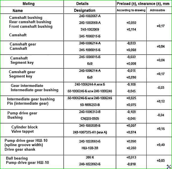
Gas distribution mechanism mounting joints
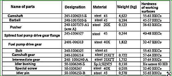
Parameters of the timing mechanism parts