Adjusting the speed mode of the D-245
To adjust the speed mode of the high-pressure fuel pump, do the following:
Connect the high and low pressure pipes to the pump installed on the stand.
Unscrew the hard stop 60 (see Fig. 1) until the intermediate lever starts moving towards the feed shut-off, followed by an additional 0.5 turn.
Turn on the test bench engine and make sure there are no leaks at the fuel line connections.
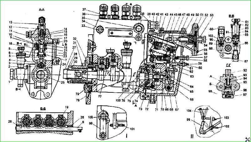
High-pressure fuel pump: I – single-lever injection pump variant; II – double-lever injection pump variant; 1 – fuel priming pump; 2 – roller-pusher bushing; 3 – pusher roller; 4 – plunger pusher; 5 – pusher adjusting bolt with lock nut; 6 – lower plate; 7 - plunger tail; 8 - plunger spring; 9 - rack; 10 - toothed ring; 11 - fuel outlet channel; 12 - spring; 13 - fitting; 14 - discharge valve; 15 - gasket; 16 - discharge valve seat; 17 - fuel supply channel; 18 - plunger sleeve; 19 - tightening screw; 20 - pin; 21 - upper plate; 22 - plunger rotary sleeve; 23 - cover; 24 - fuel injection pump housing; 25 - camshaft; 26 - rack nut; 27 - nut; 28 - washer; 29 - splined sleeve; 30 - mounting flange; 31 - key; 32 - spring; 33 - air bleed plug; 34 - bushing; 35 - bypass valve; 36 - bolt; 37 - clamp; 38, 102 - bushings; 39 - boost corrector housing; 40 - spring lever; 41 - starting enrichener spring; 42 - finger; 43 - earring; 44 - governor spring; 45 - rack rod; 46 - stop; 47 - boost corrector cover; 48 - main governor lever; 49 - pin; 50 - bushing; 51 - diaphragm; 52 - plate; 53 - boost corrector cover; 54 - rod; 55 - screw; 56 - bolt; 57 - idle spring; 58 - corrector rod; 59 - adjusting linings; 60 - rigid stop; 61 - corrector housing; 62 - bracket; 63 - bolt; 64 - heel; 65 - intermediate lever axis; 66 - intermediate lever; 67 - speed regulator housing; 68 - lever axis; 69 - weight; 70 - regulator coupling; 71 - adjusting screw; 72 - weight axis; 73 - hub; 74 - elastic drive with rubber elements; 75 - thrust washer; 76 - bearing cup; 77 - plate retainer; 78 - pump mounting plate; 79 - bearing; 80 - square bolt; 81 - handle-nut; 82 - cover; 83 - vertical cylinder; 84 - rod; 85 - fuel priming pump piston; 86 - nylon inlet valve; 87 - rotary elbow; 88 - housing; 89, 96 - springs; 90 - discharge valve; 91 - fuel priming pump; 92 - pusher; 93 - guide sleeve; 94 - rod; 95 - fuel priming pump piston; 97 - stop; 98 - plug; 99 - fuel supply control lever; 100 - control lever shaft; 101 - maximum speed adjustment screw; 103 - engine stop lever adjustment screw; 104 – Engine stop lever
Increase the pump camshaft speed above the nominal speed by 200 min -1 and make sure there are no knocks in the pump and governor.
Adjust the governor start-up time by setting the control lever to the maximum feed position and securing it.
The speed corresponding to the governor start-up time is determined by comparing the cyclic feeds measured with a sequential increase of 5 revolutions in the speed, starting from the nominal speed.
The camshaft speed should be taken as the governor start-up time, after which the cyclic feed decreases by more than 2.5 mm 3 cycle. The speed of the regulator start is 1210+5 min -1.
The start of the regulator is adjusted by the maximum speed screw, screwed into the lug of the regulator body.
The screw limits the movement of the fuel supply control lever. The adjusting screw is fixed with a lock nut and sealed.
Screwing in the maximum speed adjusting screw reduces the start speed, unscrewing it increases the speed.
If it is difficult to adjust the start of the regulator in the described way, you can use a change in the position of the hard stop or change the length of the regulator spring - by changing the number of working turns using an earring.
In this case, the end turns of the spring must be threaded through at least two holes.
After adjusting the start of the regulator, carefully lock the maximum speed adjusting screw and the hard stop with nuts. Maximum idle speed - 1250±5 min -1.
Complete shutdown of fuel supply through injectors - no more than 1350 min -1.
Adjustment of maximum idle speed - 1250±5 ... idle running is carried out by screwing or unscrewing the regulator spring from the earring, while it is necessary to re-adjust the start of the regulator action.
Check the complete shutdown of the fuel supply through the injectors, which should be at a rotation speed of the camshaft of the pump of no more than 1350 min -1.
Fuel flow through the injectors is allowed in an amount of no more than 1/4 of the idle supply at the maximum permissible rotation speed for automatic shutdown by the fuel supply regulator.
")

")
")
")
")
")
")
")