Assembly and installation of the ZIL-5301 cardan transmission
Before installation on the vehicle, the cardan transmission must be fully assembled
Before assembly, the cardan transmission parts must be washed and blown with compressed air.
Assembly must be carried out taking into account the marks made during disassembly
It should be borne in mind that difficulties may arise when installing the cardan transmission due to the formation of an air lock in the splined connection.
To eliminate the resulting air lock, it is necessary to unscrew the nut and remove excess air from the splined connection, for which: pump the sliding fork in the splined sleeve 3-4 times; set the installation distance between the hinge centers.
After waiting 20÷25 sec, tighten the splined connection nut.
Assembling the cardan joints
Before pressing the end seals onto the crosspiece tenons, it is necessary to put 1.1÷1.3 g of 158 or 158M or "Litol-24" grease into each blind hole of the tenon, and 3.7-4.2 g of the same grease into each needle bearing.
The hinge assembly can be performed in one of two ways.
1. The end seal is pre-pressed onto two adjacent crosspiece tenons, after which the crosspiece is installed into the fork (flange).
The remaining end seals are installed onto the tenons through the bearing holes in the forks (flanges) and pressed onto the tenon seat belts.
2. The crosspiece without end seals is installed in the fork (flange), after which end seals are pressed onto the crosspiece pins through the holes for the bearings in the forks (flanges).
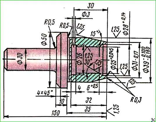
A special mandrel must be used to press the end seal onto the tenon seat belt (Fig. 1).
If there are no end seals in the spare parts kit, it is permissible to install bearings without an end seal, but the service life of the universal joint will be significantly reduced.
Press in the needle bearings of the cardan shaft joints using a universal puller (see Fig. 2).
Install the support plates so that the protrusion on the plate fits into the groove of the end face of the needle bearing housing.
Install two lock plates, secure with bolts (tightening torque 14÷18 Nm).
Lock the bolts with the tabs of the lock plate, bending them at the edges of the bolts.
Assemble the remaining joints in the same way.
Installing the intermediate shaft support
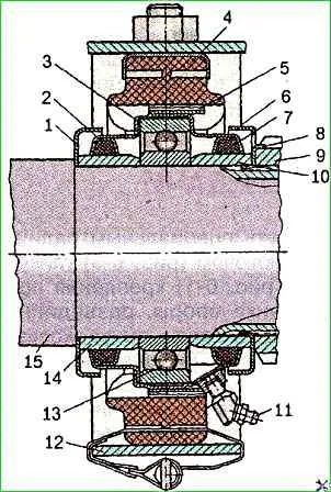
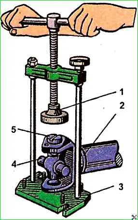
Press the support bearing assembly with cover 3 (see Fig. 3), sealing rings 2 and 7, spacer sleeves 10 and 14 and support cushion 4 onto the splined sleeve using a hammer and a mandrel (Fig. 4), which rests against the spacer sleeve 10 (see Fig. 3).
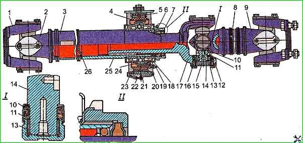
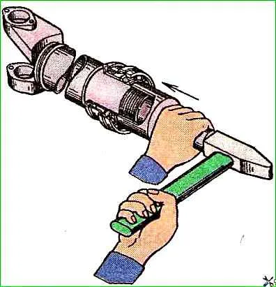
Put on the end of the sliding fork: nut 6 (see Fig. 5), split rubber washer cuff, rubber cuff, felt ring and split washers of the felt ring.
Insert the splined end of the sliding fork 17 into the splined sleeve 25 and, having screwed on the nut 6, secure the intermediate support, then lock the nut by bending the stopper into the groove of the nut.
Before assembling the splined connection, put VNIINP-242 GOST 20421-75 grease into the cavity of the splined sleeve.
Balancing the cardan transmission
The cardan transmission must be balanced when replacing or repairing the fork, fork-flange, sliding fork, splined sleeve or after straightening the shafts.
In this case, the cardan transmission is installed on the balancing machine as follows: the outer forks-flanges are attached to the adapters of the balancing machine with installation on the centering flanges of the forks-flanges, the intermediate support of the cardan shaft is installed in a special rest.
The cardan transmission is balanced from the side of the front and rear hinges, as well as from the side of the middle hinge.
The permissible imbalance of the cardan transmission must not exceed the values specified in the technical specifications.
Two arrows are applied to mark the relative position of the balanced set: one on the sliding fork, the other on the splined sleeve of the intermediate cardan shaft.
When assembling the cardan transmission, it is necessary that the indicated arrows are located opposite each other.
Installing the cardan transmission
Fasten the fork-flange of the cardan transmission on the flange of the rear axle gearbox by tightening the bolt connection.
Raise the cardan transmission and secure the intermediate support to the frame crossmember, putting the locking bracket and bracket on the support, tighten the bolts.
In this case, the support cushion should be perpendicular to the axis of the intermediate cardan shaft.
Tie the lower edge of the support cushion to the bracket with a band clamp.
Connect the fork-flange of the intermediate cardan shaft to the flange of the secondary shaft of the gearbox. The tightening torque of these connections is 80÷100 Nm.