Removing and disassembling the ZIL-5301 cardan transmission
To remove the cardan transmission from the vehicle, unscrew the nuts securing the rear fork-flange of the cardan shaft, remove the washers and remove the bolts from the flange holes, while supporting the cardan shaft.
After this, lower the end of the shaft down onto a platform or wooden pad.
Unscrew the bolts securing the intermediate shaft support to the frame, unscrew the nuts securing the bolts securing the front fork-flange, and remove the cardan transmission from the vehicle.
When removing the cardan shaft or installing the shaft on a bus, do not use a mounting blade or other objects inserted into the joint to turn the cardan shaft, as this will damage the end seal and cause premature failure of the cardan hinges.
Before disassembling, the cardan transmission must be cleaned of dirt and washed in a degreasing solution or in hot water.
For disassembling, the cardan transmission can be installed on a mechanic's workbench.
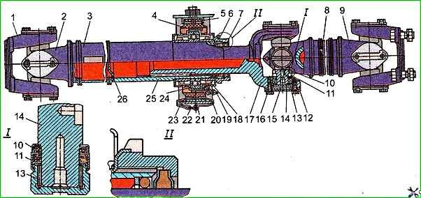
Remove clamp band 20, locking bracket 5 of the cushion and support bracket 23
Bend back stopper 8
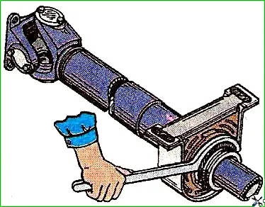
And unscrew nut 6 (see Fig. 1) of the support bearing fastening with a special radius key, disconnect the cardan shafts, removing sliding fork 17 from splined sleeve 25.
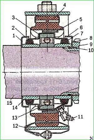
Remove the rubber cushion 4 and rear reflector 6 (see Fig. 2) from the intermediate propeller shaft support bearing
Using a puller model И 803.25.00 or 20П-7968, press off the ball bearing 13 (see Fig. 2) of the support assembly with cover 3, seals 2 and 7 and spacer sleeve 10.
It is recommended to disassemble the universal joint only in case of failure of its parts.
It is recommended to disassemble the cardan joint only in case of failure of its parts.
Before disassembling the cardan joints of a cardan transmission that has been in operation for a long time, it is recommended to generously moisten the bearing installation sites with kerosene using a brush.
When disassembling cardan joints, mark the relative positions of the parts, bend back the ears of the lock plates, unscrew the bolts securing these plates and remove the lock and support plates.
Then disassemble the joint.
It is strictly forbidden to use a hammer when disassembling and assembling the cardan joint, since this disrupts the alignment of the holes in the forks for the bearings, which sharply reduces the service life of the cardan joint.
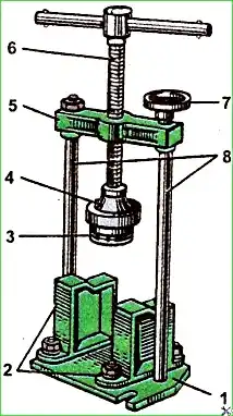
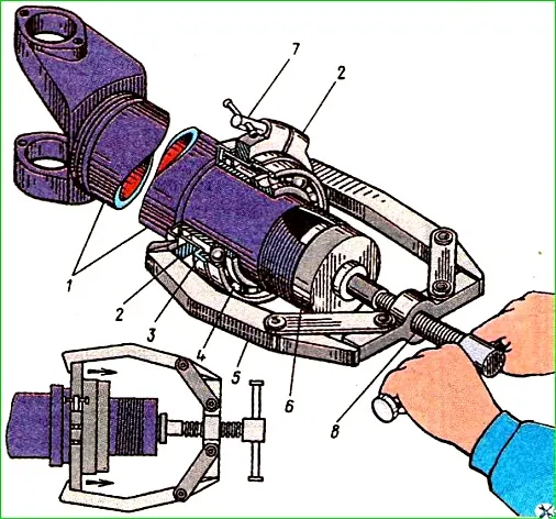
Disassembly of the cardan shaft joints should be carried out using a universal puller model I 803.26.000 (Fig. 5), which eliminates deformation of the forks, breakage of the bearings and allows easy disassembly of the joint.
Base 1 of the puller has lugs for fixing the puller on a metalworking bench.
Supports 2, which have a base surface for the forks, flanges and crosspieces of the cardan joints, are equipped with oval holes, which in the known th limits allow the supports to be moved on the base depending on the size of the hinge being disassembled.
The removable cup 3 is a section of pipe with holes of different diameters at both ends.
Using an external thread, the cup is secured to the tip of the stop screw either at one end or the other depending on the size of the bearing being removed.
The support columns 8, screwed into the hole in the base, carry a crossbar 5 with a stop screw 6 and a clamping nut 7.
The puller allows the removable cup 3 to rest against the eye of one of the forks when the stop screw 6 is rotated, while the second fork of the hinge lies on the supports 2.
With further rotation of the screw, the cup 3 comes closer to the supports, and the crosspiece bearing enters the cavity cup.
The stop screw continues to rotate until the bearing easily comes out of the eye hole.
The joint is disassembled in two steps:
First, one of the forks is installed on the supports (Fig. 6, (a)) and the bearings are pressed out of the fork connected to it (which we will conventionally call the first fork).
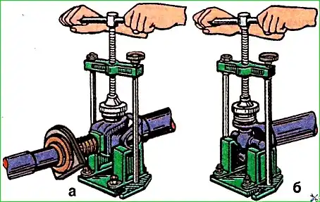
During the second step, special bevels of the support the crosspiece pins of the first fork (from which the bearings have already been pressed out) are installed and the bearings are pressed out of the second fork (Fig. 6,(б)).
To align and hold the cardan pipes when working with pullers, you can use stands.
The universal puller is also used to assemble cardan joints.
In this case, the removable cup 3 (see Fig. 5) is not used.
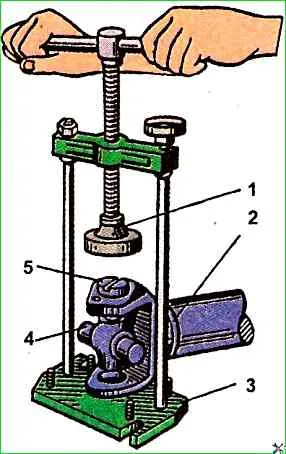
Bearings are pressed in using the flat part 4 of head 1 (Fig. 7) of the thrust screw with supports 2 removed (see Fig. 5).
The end seals should be pressed off from two adjacent pins carefully so as not to damage the end seals remaining on the other two pins of the fork.
Re-installation of end seals in the joint is not allowed, since this will not provide the required tension of the end seal on the pin seat.
")

")
")
")
")
")
")
")