Features of the cardan transmission of the ZIL-5301 vehicle
ZIL vehicles are equipped with an open cardan transmission with cardan shaft joints on needle bearings.
The cardan shafts are made of a drawn thin-walled pipe welded from cold-rolled tape
The outer diameter of the pipe is 77 mm, the inner diameter is 71 mm.
The cardan transmission consists of two cardan shafts, three joints and an intermediate support
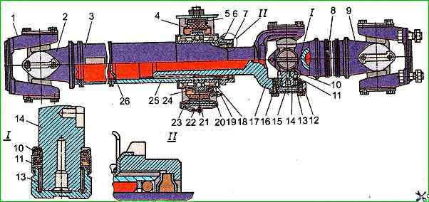
Propeller shaft: 1 - yoke-flange; 2 - yoke; 3 - intermediate propeller shaft; 4 - support cushion; 5 - cushion bracket; 6 - intermediate support bearing fastening nut; 7, 18 - seals; 8 - rear axle propeller shaft; 9 - propeller shaft yoke; 10 - mechanical seal; 11 - single-lip needle bearing cuff; 12 - lock plate; 13 - crosspiece needle bearing; 14 - crosspiece; 15 - support plate; 16 - bolt; 17 - sliding yoke; 19 - oiler for lubricating the intermediate support bearing; 20 - clamp; 21 - cotter pin; 22 - clamp lock; 23 – support bracket; 24 – ball bearing; 25 – splined sleeve; 26 – splined bushing plug
The joints of all cardan shafts are identical in design and consist of a fixed or sliding fork, a flange fork and a crosspiece installed in the fork ears on needle bearings.
The joints have a combined rubber seal consisting of an end seal pressed onto the crosspiece tenons and a single-lip cuff built into the bearing.
The crosspiece has four tenons with seat belts for installing end seals.
The crosspiece does not have through holes for lubrication.
The intermediate support has stamped steel covers pressed onto a ball bearing, installed together with the covers in the rubber support cushion.
The intermediate support is bolted to the car frame using a bracket.
The cardan transmission is balanced as an assembly. Permissible imbalance - 100 g / cm.
Requirements for cardan transmission parts
When repairing a cardan shaft, it is necessary to check the wear of the holes for needle bearings, wear of the splined connection, wear of the crosspiece pins and needle bearings, as well as its imbalance and runout.
If the wear of the holes for needle bearings of splined connections and crosspieces exceeds the dimensions permissible without repair, the worn parts should be replaced.
The runout of the end of the crosspiece pin relative to the working surface of the pin is allowed to be no more than 0.025 mm.
Checking the runout, straightening and balancing of cardan shafts should be carried out in workshops with special equipment.
The runout is checked when installing the shaft (welding) in the centers of two mandrels, which are installed in the holes under needle bearings of forks with centering on machined planes of fork ears.
The shaft runout should not exceed 0.8 mm.
If the runout is more than permissible, the shaft should be straightened under a press, installing it on supports.
Intermediate cardan shaft with support assembly
The runout of the splined sleeve surface for mounting the support bearing is allowed to be no more than 0.3, and the pipe - no more than 0.8 mm.
The runout of the intermediate shaft (welding) is checked by installing the shaft in the centers of two mandrels.
The first mandrel is installed in the holes for the needle bearings of the fork with centering on the machined planes of the fork ears.
The second mandrel is installed in the splined hole of the splined sleeve with centering on its internal diameter over a length of 100 mm and should protrude from the shaft by 115 mm.
If the neck of the splined sleeve for the intermediate cardan shaft support bearing or the splined hole of the sleeve is worn beyond the permissible dimensions, the shaft should be replaced.
If the bearing caps are crushed and the spacer sleeves of the intermediate cardan shaft support are worn beyond the dimensions permissible without repair, the caps and spacer sleeves should be replaced.