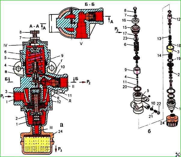
The pressure regulator (Fig. 1) is designed for automatic regulation of pressure in the pneumatic system within 0.65 - 0.8 MPa, as well as for protecting pneumatic drive units from oil contamination and excessive pressure increase in the event of failure of the regulating device
The pressure regulator is connected by a pipeline directly to the compressor; attached to the bracket with two bolts.
The atmospheric outlet of the regulator is directed downwards so that the condensate emitted by the regulator does not get on other parts of the car.
Disassembling and assembling the regulator
Fix the regulator in a vice with soft jaws by the boss of terminal 1 of the housing 5.
It is prohibited to fasten the regulator by the upper and lower parts of the housing 5, as this may lead to its deformation or destruction.
Unscrew the lock nut 7 and unscrew the adjusting screw 8, loosening the spring 6 of the balancing piston.
Then unscrew with a special 50 mm socket wrench mod. and 806.04.006 upper cover 15 and remove spring 6 and balancing piston 9 together with inlet 11 and outlet 4 valves, remove sealing cuff 20.
Unscrew lower cover 1 with noise muffler.
To remove noise muffler it is necessary to unscrew it from the lower cover and remove filter 3 with spring and unloading piston 12 assembly.
To disassemble unloading piston 12 it is necessary to remove two thrust rings 18 and 19 with round-nose pliers.
To disassemble check valve 10 it is necessary to unscrew washer 22 with round-nose pliers and remove check valve with spring 21.
After disassembling, wash the regulator parts with clean gasoline or acetone, dry and thoroughly inspect.
There should be no cracks, hairlines or other visible defects on the surface of the body parts.
The parts should be cleaned of rust and burnt-on deposits. All rubber parts must be replaced with new ones.
The procedure for assembling the regulator is the reverse of disassembling.
The threads on the lower 1 and upper 15 covers must be lubricated with graphite grease during assembly.
Adjusting and checking the pressure regulator after assembly
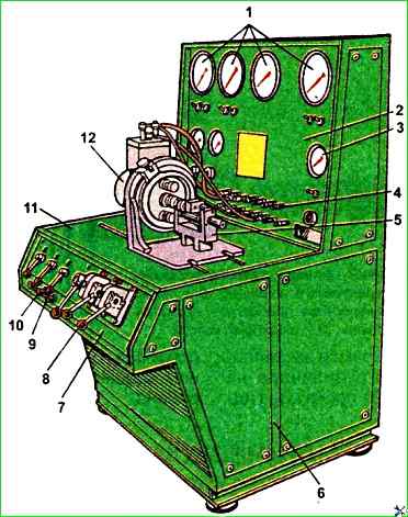
Install the pressure regulator on the test bench (see Fig. 2) and connect the device according to the diagram shown in Fig. 1), a.
Then supply and release air three times under a pressure of 1.4 MPa into terminal I. In this case, terminal V must be plugged.
If the limits of the regulated air pressure in output II do not correspond to 0.65-0.8 MPa, the pressure should be adjusted to the required limits using the adjusting bolt 8.
In this case, you should strive to achieve the upper pressure limits, since the set pressure may decrease due to the shrinkage of the springs during operation.
After adjustment, check the regulator on/off pressure three times, and then lock the adjusting bolt.
By installing adjusting washers of different thicknesses under the spring of the unloading valve, it is necessary to adjust the actuation pressure of the unloading valve 2.
To do this, block the air passage to outputs I and II using a plug.
Increase the pressure in output I three times and upon reaching the pressure 1.0-1.35 MPa the safety valve should open and air should escape through terminal III of the regulator.
After adjustment, clear the passage to terminal II.
To check the regulator for leaks, set the pressure to 0.05 MPa in terminals I and II, while checking the tightness of the inlet valve II, piston cuff 9 and relief valve 2.
The tightness of the check valve 10 is checked by setting the pressure to 0.45 MPa in terminal II. When soaping, the appearance of air bubbles is not allowed for 1 min.
")

")
")
")
")
")
")
")