The ZIL-5301 vehicle with division along the sides uses a flangeless two-cavity brake chamber, designed to act on the master brake cylinder and installed together with it on a bracket on the front panel of the cabin under the hood of the vehicle
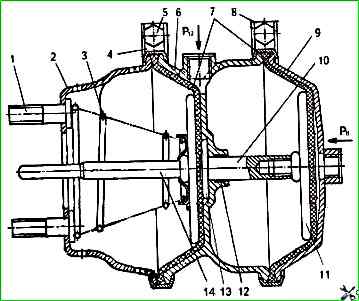
The design of the brake chamber is shown in Fig. 1.
Before disassembling, the two-cavity brake chamber must be removed from the bracket and disconnected from the master brake cylinder.
To disassemble the chamber
- - it is necessary to clamp it in the device with a screw;
- - unscrew the bolts 5 (see Fig. 1) of the clamp 4;
- - remove the clamps and, releasing the screw of the device, since the spring 3 creates a force of more than 50 N, separate the housings 2 and 6. Remove the rod 14, the membrane 7 and the spring 3.
Then it is necessary to unscrew the bolts 5 and remove the clamps 8, after which remove the membrane and cover 9.
To disassemble the pusher 10, if it is necessary to replace the guide of the pusher 12, it is necessary to clamp it in a vice with soft jaws by the disk 11, unscrew the pusher 13.
If this cannot be done, then it is necessary to heat the plunger to a temperature of approximately 200 °C, since it is assembled on UG-6 anaerobic sealant, on which it must also be installed during reassembly.
When assembling the chamber
First, it is necessary to assemble the housing 6 with the plunger 10, install the secondary chamber membrane, cover 9 and install the clamp 8, securing it with a bolt, nut and spring washer.
Then install the chamber in the device with the screw, install the primary chamber membrane, rod 14, spring 3 and housing 2, clamp them in the device and secure with clamp 4.
During assembly, special attention must be paid to the correct relative position of the housings, cover and membranes.
After repair, the two-cavity chamber must be checked for operability and tightness.
The check must be carried out according to the diagram shown in Fig. 1.
To check the functionality of the chamber, air must be supplied three times under a pressure of 0.75 MPa alternately to terminals P and P12 of the device.
The rod must quickly extend and return to its original position without jamming.
To check for leaks, wet the joints of the cover and the body with soap emulsion, supply air under a pressure of 0.75 MPa alternately to terminals P and P12 of the device.
To eliminate air leakage, tighten the clamp mounting bolts.
If the leak continues, replace the membrane.
")

")
")
")
")
")
")
")