The oil-moisture separator is designed to clean compressed air from moisture and oil, and to prevent condensate from freezing in air lines and pneumatic drive units.
Disassembling and assembling the oil-moisture separator
To disassemble the oil-moisture separator, unscrew screw 4 and remove cap 1.
Then remove filter 3 and cup 2 with adsorbent granules.
To disassemble valves 8 and 10, use round-nose pliers to unscrew the thrust washers of the springs, after which the valves can be easily removed from the housing.
Maintenance of the oil-moisture separator consists of washing filter 3 using washing powder or gasoline.
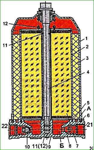
It is also recommended to calcine cup 2 with the adsorbing element at a temperature of 200 °C for 2 hours.
ATTENTION! It is prohibited to wash the glass with adsorbent granules.
The oil-moisture separator is assembled in the reverse order of disassembly.
Testing the oil-moisture separator
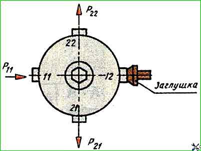
Install the oil-moisture separator on the test bench and connect it according to the diagram shown in Fig. 2.
Then supply and release air three times under a pressure of 0.75 MPa into outlet 11
Supply air under a pressure of P11 = 0.75 MPa.
The pressure in outlets 21 and 22 should become at least 0.73 MPa in no more than 5 s.
Reduce the pressure in outlet 11 to zero.
The pressure in outlet 21 should not drop, and the pressure drop in outlet 22, with a 6 l container connected to it, to a pressure of 0.2 MPa should be in no less than 15 sec.
Check the moisture-oil separator for leaks.
The check is performed at a pressure of P11 = 0.75 MPa in output 11.
When installing the moisture-oil separator on a bus, output 22 must be connected to the regeneration cylinder; output 12 - to the pressure regulator and output 21 - to the vehicle's brake system.