The steering gear must be delivered to the work site where the disassembly and repair of the steering gear will be performed only after it has been thoroughly cleaned of dirt and washed on the outside with kerosene or another degreasing liquid.
When starting the disassembly, it is necessary to keep in mind that in order to prevent external leakage after disassembling the steering gear, it is necessary to replace all rubber sealing rings and cuffs.
The steering gear must be disassembled only in case of emergency.
This operation must be performed by a qualified mechanic in conditions of complete cleanliness.
The following sequence of disassembling the steering gear is recommended.
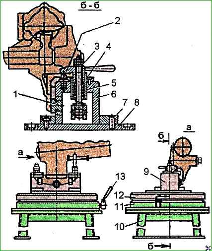
Stand for assembling and disassembling the power steering mechanism: 1 - stop; 2 - locking pin; 3 - clamp with handle assembly; 4 - spring; 5 - bushing; 6 - housing; 7 - mounting pin; 8 - plate; 9 - device for fastening the steering gear housing; 10 - stand base; 11 - fixed plate; 12 - rotating plate; 13 – rotary plate locking mechanism lever
Secure the steering gear on a stand or in a vice.
Set the propeller shaft to the middle position using a special key model И803.03.13.
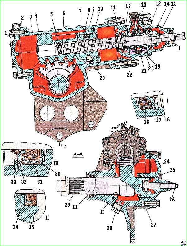
Steering gear parts: 1 – lower cover; 2 – sealing ring; 3 – steering gear housing; 4 – piston-rack; 5 – split sealing ring; 6 – steering gear screw; 7 - Ball nut; 8 - Groove; 9 - Ball; 10 - Sealing (fluoroplastic) and retaining (rubber) rings; 11 - Intermediate cover; 12 - Thrust ball bearing; 13 - Safety valve; 14 - Adjusting nut; 15 - Top cover; 16, 33 - Retaining rings; 17, 32 - Outer seals; 18, 27, 31, 35 - Sealing cuffs; 19 - Control valve body; 20 - Spool valve; 21 - Spring; 22 - Reaction plunger; 23 - Set screw; 24 - Side cover; 25 - Thrust washer; 26 - Adjusting screw; 28 - Drain plug with magnet; 29 - Piston arm shaft; 30 - Thrust ring; 34 – thrust washer
Unscrew the bolts securing the side cover 24 (Fig. 2) and remove it together with the bipod shaft 29, being careful not to damage the sealing cuffs with the splined end
Remove the sealing ring, unscrew the adjusting screw from the cover and remove the cover from the bipod shaft.
To remove the adjusting screw, use round-nose pliers to remove the retaining ring and adjusting screw 26 with the thrust 25 and adjusting washers.
Unscrew the bolts securing the upper cover 5 (Fig. 3) and remove the cover assembly with the seals 2 and 3.
Remove the sealing ring 6. If necessary, press the seals 2 and 3 out of the socket, removing the retaining ring 4.
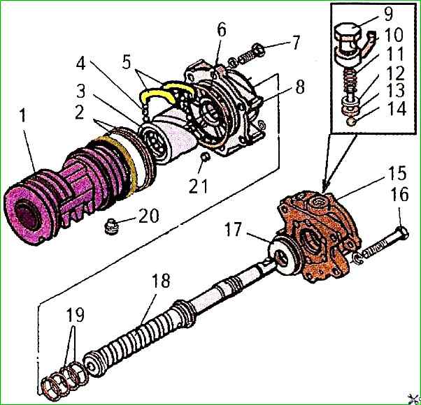
Steering gear parts: 1 – piston-rack; 2 – piston ring; 3 – ball nut; 4 – ball; 5 - groove; 6 - sealing rings; 7, 16 - bolts; 8 - intermediate cover; 9 - bypass valve bolt; 10 - square; 11 - spring; 12 - adjusting lining; 13 - spring guide; 14 - safety valve ball; 15 - control valve; 17 - thrust ball bearing; 18 - steering gear screw; 19 - sealing rings; 20 - set screw; 21 - bushing
Unlock and unscrew nut 7, remove spring washer 8 and thrust bearing 9.
When unscrewing nut 7, the steering gear screw shaft must be held from turning using a special key mod. And 803.03.13.
Unscrew bolts 16 (Fig. 4) securing the control valve body 15 and remove it from screw 18.
Remove the second thrust bearing 17 and remove the sealing ring 6 from the groove of the intermediate cover 8.
The control valve body, spool and plungers are individually selected at the factory.
Therefore, when disassembling, their completeness must not be violated and disassemble only in extreme cases.
Remove twelve reaction plungers 10 (see Fig. 3), six reaction springs 1 and spool 11 from the valve body (on both sides). The valve parts must be carefully laid out on a tray or pallet.
If necessary, unscrew the oil supply nipple and safety valve 13 (see Fig. 2) from the body.
Unscrew the bolts securing the lower cover 1 of the crankcase, remove the cover and sealing ring 2.
Unscrew the bolt 7 (see Fig. 4) securing the intermediate cover 8, remove the steering screw 18 from the cylinder in assembly with the intermediate cover and the rack-piston 1, protecting the piston sealing rings from damage.
Press out the cuff 31 (see Fig. 2) with protective ring 30, having first removed retaining ring 33, and if necessary, the pitman arm shaft sleeve.
To disassemble, secure the rack-piston assembly with the screw on a stand or in a bench vice with soft jaws and disassemble the unit in the following sequence.

Release the set screws 20 from the punch (see Fig. 4), fastening the rack-piston 1 with the ball nut 3.
Unscrew using a special key with a sufficiently large shoulder or using a special device mod. И806.03.300 two set screws 20 (see Fig. 4) securing the ball nut.

Using a special ring (see Fig. 5), press out the ball nut 3 with the screw 18 from the piston-rack 1, holding the grooves and balls from falling out, and remove the grooves by turning the screw relative to the nut in one direction or another to remove the balls
Remove the intermediate cover 8. If necessary, remove it from the screw and rack-piston sealing rings.
After disassembling, all steering gear parts must be washed in a cleaning solution MS-6 or MS-8 Tu 6-15-978-76 and blown with compressed air.
Check the condition of the steering gear parts in accordance with the defecation map, damaged and worn parts should be replaced.
")

")
")
")
")
")
")
")