Adjusting the thrust bearings of the ZIL-5301 steering gear
To adjust the bearings, do the following:
Unscrew the bolts securing the upper cover and remove it.
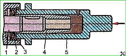
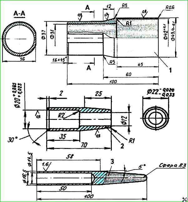
To avoid damaging the cuff and sealing ring, use a safety mandrel 4 (Fig. 1) placed on the end of the screw;

Unscrew the control valve mounting bolts;
Using a special key, unscrew the steering propeller together with the control valve body by 10÷15 mm so that the valve body rotates freely on thrust bearings without touching the intermediate cover;
Check the axial play of the steering propeller in the ball nut; if it exceeds 0.2 mm, disassemble the steering gear and replace the screw pair (screw-nut kit spare parts number 130-3401355).
If the axial play of the steering screw does not exceed 0.2 mm, the nut of the thrust bearings should be unlocked and tightened so that the torque of the valve body relative to the steering screw is 0.6 ÷ 0.85 Nm.
The torque can be checked with a spring dynamometer, which is hooked at the same time from the holes for the bolts of the control valve body.
In this case, the torque of 0.6 ÷ 0.85 Nm corresponds to the readings of the dynamometer of 11 ÷ 15 N.
If the rotation of the control valve body relative to the screw is not smooth, it is necessary to unscrew the nut, remove the body and inspect the condition of the raceways of the thrust bearings bearings.
When removing the housing, be careful that the spool valve and all reaction plungers remain in place, as they are individually matched at the factory.
Replace (if necessary) the thrust bearings and reinstall the control valve housing.
The bearings must be installed so that their larger diameter rings face the spool valve.
The conical disc spring must be located between the ball bearing and the nut, with the concave surface facing the thrust bearing.
After adjusting the tightening of the nut, its flange must be pressed into the screw groove without breaking.
After this adjustment, the steering gear must be assembled and checked.
Adjusting the gear engagement on a car
To adjust the gear engagement, it is necessary to:
Disconnect the longitudinal tie rod from the steering arm;
Loosen the nut securing the adjusting screw located in the central boss of the side cover of the steering gear;
Adjust the gear engagement by turning the adjusting screw with a key by the square head.
It should be borne in mind that when turning the screw clockwise, the tension in the gear engagement will increase;
After completing the adjustment, tighten the lock nut to a torque of 40÷45 Nm, holding the adjusting screw by its square head with a key from turning;
Check the steering wheel rotation torques again and attach the longitudinal steering rod.
Replacing the cuff of the upper cover of the steering gear on a car
Replacing the cuff of the upper cover can be done on a car, provided that the workplace is clean. If this is not possible, remove the steering gear from the bus and replace the cuff in a workshop.
To replace the cuff of the upper cover, do the following:
Drain the oil from the power steering system;
Disconnect the steering cardan shaft;
Wash the control valve body and the upper cover in gasoline;
Unscrew the upper cover mounting bolts and remove it, being careful not to damage the outer cuff.
Cover the end of the control valve with clean paper or a napkin;
Remove the upper cover retaining ring with pliers, remove the washer, outer seal and cuff, then wash the mounting hole with gasoline;
Lubricate the outer surface of the new cuff with oil and press it in using mandrel 5 (see Fig. 1), install the outer cuff and retaining ring;
Check whether the retaining ring has entered the groove of the top cover completely;
Wash the assembled top cover, replace the rubber sealing ring on its end.
To prevent the rubber ring from falling out when installing the cover, it is recommended to lubricate it with consistent grease (it is permissible to install the top cover with the old rubber ring if it is in satisfactory condition);
Remove the protective paper or napkin from the end of the control valve and wash it with gasoline, preventing dirt from getting inside the mechanism.

Put mandrel 4 (see Fig. 2) on the end of the steering screw, protecting the seal from damage by the edges of the screw groove;
Observing all precautions against dirt ingress, install the top cover in place and tighten the mounting bolts, tightening torque - 21÷28 Nm;
Remove mandrel 4 and attach the propeller shaft;
Flush and fill the system with oil.


