Disassembling the ZIL-5301 power steering pump and its drive
Disassemble the pump only if the flow rate is insufficient (volumetric efficiency below 0.6)
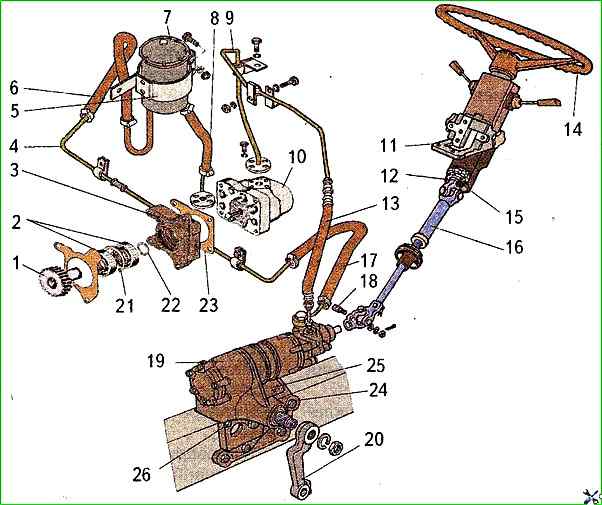
Before disassembling the pump, disconnect the flanges securing the oil supply and return pipes to the pump.
Unscrew the bolts securing the pump to the gear cover shield and remove the pump from the engine together with the drive.
Drain the oil from the pump and thoroughly clean its outer surface.
Remove the hydraulic pump drive assembly from the pump shaft using a copper drift or hydraulic press.

The pump is disassembled and tested using a special device shown in Figure 1 or in a vice in the following order:
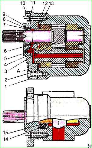
Unscrew bolts 10 (Fig. 2)
Using round-nose pliers, remove retaining ring 9 and remove cover 1 of the pump together with cuff 8 and support ring 7;
Dismantle cuff 12, seal 15 and liner 14;
Remove the drive gear 3 together with the bushing 6.
To disassemble the hydraulic pump drive, remove the thrust ring 22 (Fig. 3) with round-nose pliers and press out the gear 1 together with the bearing with a hydraulic press.
Remove the thrust ring 21 from the bearing housing 3 and press out the ball bearing;
Press the bearing off the pump drive gear.
All pump parts are non-interchangeable, so when disassembling it, mark all the bushings so that they can be installed in their original place.
After disassembling the hydraulic pump and its drive, thoroughly wash, inspect all parts and inspect them for defects.
On the surface of the ends of the bushings and gears there should be no noticeable scoring or wear.
A decrease in the bushing height by more than 0.2 mm is not allowed, however, in case of minor wear, they can be ground in with GOI paste.
Repair of the pumping unit parts (bushings and gears) is usually impossible.
Therefore, these parts are replaced with a repair kit produced by the manufacturer.
All seals and gaskets of the pump and its drive must be replaced during assembly.
The pump is assembled in the reverse order of disassembly.
After repair, the pump must be tested for performance on a special stand.