When removing the gearbox, it is necessary to unscrew the bolts securing the cabin floor cover, remove it and unscrew the flange for fastening the cardan shaft
Unscrew the bolts securing the PGU to the bracket, disconnect the pusher from the clutch fork lever and, without disconnecting the pipelines, secure the PGU to the car so as not to damage the pipelines.
Remove the crankcase with the gearshift lever.
Disconnect the intermediate support bracket from the frame crossmember and lower the cardan shaft, disconnect the speedometer shaft.
Unscrew the nuts of the studs securing the gearbox to the clutch housing using a spanner.
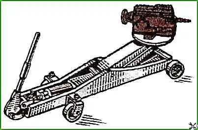
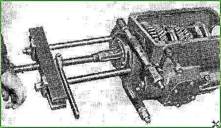
Disconnect the gearbox from the clutch housing and remove it using a jack trolley with a special puller 32P-1270.
After removing the gearbox from the car, you need to install the housing with the gearbox control lever in place.
Before disassembling, you need to drain the oil, unscrew the plug from the drain hole, then clean and wash the gearbox from the outside.
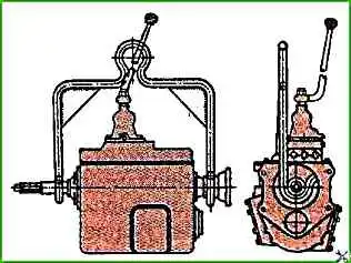
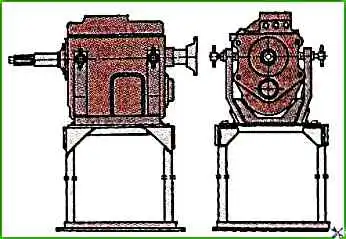
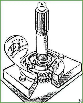
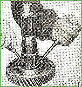
Using the suspension (Fig. 2), hook the gearbox, lift it with a hoist and install it on the device (Fig. 3) for disassembling and assembling gearboxes.
The gearbox is installed on the bus in the reverse order of its removal.
Gearbox disassembly
To remove and disassemble the gearshift lever tip housing, unscrew the first gear and reverse gear fuse
Unscrew the four crankcase mounting bolts, remove the crankcase with the lever assembly and the crankcase gasket.
Unscrew the nut from the tip, remove the lever and take out the key.
Secure the lever tip housing in a vice, pointing the tip down.
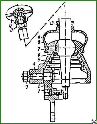
Unscrew nut 3 (Fig. 5) securing the intermediate lever axle, holding it while this axle head, remove the spring washer and axle 4 with the intermediate lever.
Then remove the axle from the lever hole and the fuse.
Remove spring 5 from the crankcase, remove support 6 of the lever, remove the lever 10 assembly and the lock 7 of the lever.
Removing and disassembling the gearshift mechanism
Unscrew the gearbox cover mounting bolts, remove the cover assembly with the gearshift mechanism, remove the cover gasket.
If the gasket is stuck, carefully separate it with a screwdriver or other tool.
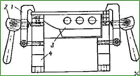
The gearbox shift mechanism is disassembled in the device (Fig. 6), in which the cover is fixed in a position convenient for disassembly.
If there is no device, the cover can be disassembled by fixing the cover in a vice.
The gear shift mechanism must be disassembled in the following order.
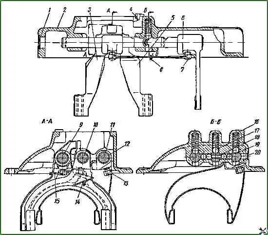
Unpin the locking bolts securing the forks and safety heads on rods 9, 10, and 11 (Fig. 7), unscrew the locking screws securing the forks and the bolts securing the rod heads.
Using a ratchet, move one gear shift rod and press out the plug from the socket.
Moving the rod, remove the fork and, holding the locking balls with one hand, remove the rod with the other hand.
In the same way, remove the other two gearshift rods.
Removing and disassembling the primary shaft
Disconnect the return spring from the clutch release bearing sleeve, remove the sleeve with the bearing assembly.
Unscrew the four bolts securing the front primary shaft bearing cover and remove the cover with the gasket.
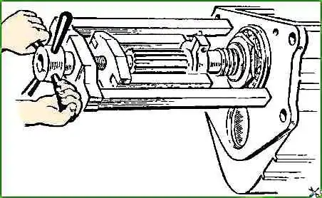
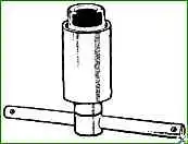
To remove the input shaft from the crankcase seat, press out the ball bearing using the 40P-5019 puller (Fig. 8) and remove the shaft with the bearing assembly.
(Usually the input shaft is easily pressed out without a puller, using two screwdrivers)
Remove the locking rings (Fig. 9) and press the bearing using the fixture.
Removing and disassembling the secondary shaft
Having locked the first gear pinion with a handle, unscrew the secondary shaft flange nut, press flange.
Unscrew the bolts securing the secondary shaft cover and remove the cover with the gasket.
Remove the drive shaft from the end of the secondary shaft speedometer drive gear.
Press out the secondary shaft bearing together with the shaft from the gearbox housing socket using a mandrel and a hammer.
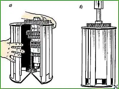
Press out the secondary shaft bearing using a device (Fig. 10), remove the secondary shaft from the gearbox housing complete with gears and synchronizers (Fig. 11,a).
Remove synchronizer 1 of the fourth and fifth gear, gear 12 of first gear.
Using two screwdrivers, remove the locking ring 2 of the fourth gear pinion mount.
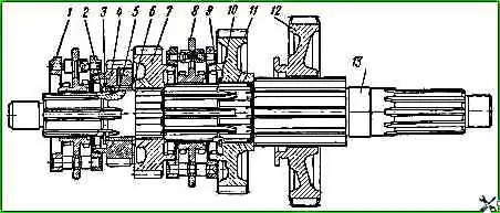
Remove thrust washer 3 together with gear 4 of fourth gear and steel bushing 5 together with stopper, thrust washer 6 and gear 7 of third gear, synchronizer 8 of second and third gears.
Using two screwdrivers, remove the locking ring of the second gear gear.
Remove thrust washer and second gear gear. Synchronizers should not be disassembled unless necessary.
Removing and disassembling the intermediate shaft and reverse gear block
Unscrew the reverse gear block axle stopper bolt, remove the stopper, and remove the block axle from the crankcase.
To press out axle 55 of the reverse gear block, use puller model I.803.20.00 (Fig. 13).
Unscrew the four bolts securing the intermediate shaft rear bearing cover, remove the cover with the gasket, bend the thin edge of the nut, lock the intermediate shaft gear with a handle and unscrew the rear bearing mounting nut.
Press the rear bearing together with the intermediate shaft out of the crankcase seat, move the shaft with gears along the axis towards the bearing.
Press off the intermediate shaft rear bearing using a puller.
The method for pressing this bearing off the shaft is the same as pressing off the bearing from the secondary shaft.
Remove the intermediate shaft with gears from the crankcase by hand.
Remove the outer ring of the intermediate shaft bearing from the crankcase seat.
If necessary, knock out the plug using a mandrel, covering the front bearing, and remove the retaining ring.
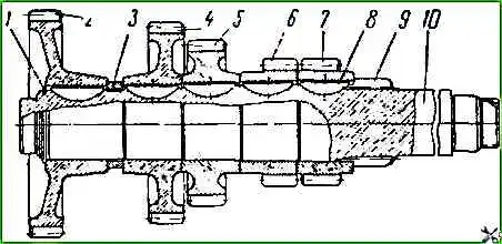
To disassemble the intermediate shaft, press off the inner bearing ring with rollers, remove the lock ring 1 (Fig. 15), press off all the gears from the shaft and remove the keys from the grooves.
The gears can be pressed in using a device or using pads on a press.
The last two gears 6 reverse and 7 second gear must be pressed together.
Checking the gearbox parts
The gearbox housing is cast from gray cast iron grade SCh24 GOST 1412-85.
After removing the parts mating with it from the gearbox housing, it is necessary to carefully check the condition of the mating surfaces, the absence of cracks and the amount of wear of the bearing holes
Cracks and holes in the gearbox housing are a rejection sign.
If the bearing holes are worn beyond the permissible dimensions, the gearbox housing must be replaced.
Damage to the threads in the housing holes is allowed within no more than two threads.
The runout of the front and rear ends of the housing relative to the common axis of the secondary shaft bearing holes is allowed within 0.08-0.15 mm.
The diameters of the holes in the intermediate and secondary shaft housings and the deviation from the common plane passing through them must not exceed 0.07-0.12 mm along the entire length of the housing.
The non-flatness of the remaining mating surfaces of the gearbox housing must be within 0.15-0.30 mm.
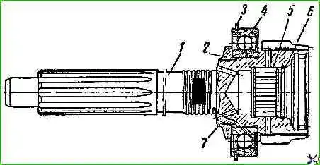
Primary shaft with a toothed rim, constant mesh gears and a splined hole.
The primary shaft is made of 25KhGM steel, the depth of the nitrocarburized layer is 0.6-0.8 mm, the hardness of the surface layer is НРСэ 61-66, the hardness of the core is НВСэ37-46.
If the journals and splines of the shaft are worn beyond the dimensions permissible without repair, the primary shaft should be replaced.
Worn journals of the shaft can be repaired by chroming with subsequent processing to nominal dimensions.
The runout of the inner hole of the new primary shaft relative to the journals for bearings is allowed to be no more than 0.02 mm.
If there is a bend or twisting, the shaft is subject to replacement.
The teeth of the primary shaft gear must not have cracks.
Minor nicks, burrs and chips on the ends of the teeth should be cleaned.
The secondary shaft is made of 25KhGM steel, the depth of nitrocarburization is 0.8-1.1 mm, the hardness of the surface layer is HVSE 61-66, the hardness of the core is HRCe 37-46.
The runout of the secondary shaft journals relative to the axis is allowed to be no more than 0.05 mm.
The use of journals with a chipped cemented layer of fatigue nature is not allowed.
Secondary shaft gears. The runout of the ends of the gearbox gears is allowed to be no more than 0.05 mm.
If there are cracks on the gears, large wear teeth and splines of the gear should be replaced.
Minor chips on the ends of the teeth should be cleaned. Chips on the working surface are not allowed.
Gearbox synchronizers
Synchronizer carriages are made of 25KhGT steel, nitrocarburizing depth 0.7-0.9 mm, surface layer hardness НРСэ 61-66, core hardness НЯСэ 37-46.
Conical rings - brass, stamped.
If there is wear of parts and loss of elasticity of the springs, the synchronizer should be replaced as an assembly. For a new synchronizer, end and radial runout of the carriage up to 0.1 mm is allowed.
Intermediate shaft. The intermediate shaft is made of 25KhGM steel, the nitrocarburizing depth is 0.8-1.1 mm, the surface layer hardness is NRSE 58..61, the core hardness is NRSE 35-45.
The runout of the intermediate shaft journals relative to the axis is allowed to be no more than 0.04 mm.
Faulty shaft journals can be repaired by chroming with their subsequent processing to nominal dimensions.
Intermediate shaft gears
The requirements for repair of the intermediate shaft gears are similar to the requirements for the secondary shaft gears.
Gear block and axis of the reverse gear block. The gear block is made of 25KhGM steel, the nitrocarburizing depth is 0.5-0.8 mm, the surface hardness is layer - HRC 58-61, core hardness - HRC 37-46.
The requirements for repairing the gear block are similar to the requirements for repairing the gears of the secondary and intermediate shafts.
Gearbox housing cover with gear shift mechanism
Cracks and chips are not allowed on the gearbox cover.
If the holes in the cover for the gear shift rods are worn, the cover should be replaced or repaired by installing bushings.
The bending of the gear shift rods is allowed to be no more than 0.1 mm. Bent rods can be repaired by straightening.
Shift rods worn beyond the permissible dimensions should be replaced or restored by chroming with subsequent processing.
Wear of the grooves in the rods for the locking balls is allowed such that the clearance between the profile template and the groove does not exceed 0.6 mm.
If the specified tolerance is exceeded, the rods should be replaced.
If there are cracks and breaks on the forks, heads and gear shift lever, they should be replaced.
Bent forks and gear shift levers can be repaired by straightening.
If the shift fork tabs are worn beyond the permissible size, the forks should be replaced.
If the groove in the forks and head for the gear shift lever is worn, the holes in the forks and head for the gear shift rod are worn, their should be replaced.
If the groove under the gear shift lever lock is worn, the lever should be replaced.