Bleeding air from the ZIL-5301 clutch control system
The hydraulic system of the clutch control mechanism consists of a master cylinder, an actuator cylinder with a pneumatic booster, a flexible hose and a pipeline
To prevent leakage of working fluid and air from entering the hydraulic system, it is necessary to carefully monitor the tightening of all threaded connections of the system.
In the event of a leak in the hydraulic system (air entering and forming air locks), it must be sealed and re-bled.
Remember that it will be impossible to bleed the system if there is no free play of the master cylinder piston pusher, since the pusher and piston are a shut-off valve through which the hydraulic system is replenished with fluid as needed, and if there is no free play of the pusher, it will be constantly closed.
The same thing happens when jamming pedal, which its release spring is not able to raise to the extreme upper position.
Bleeding can be carried out both with and without compressed air in the system.
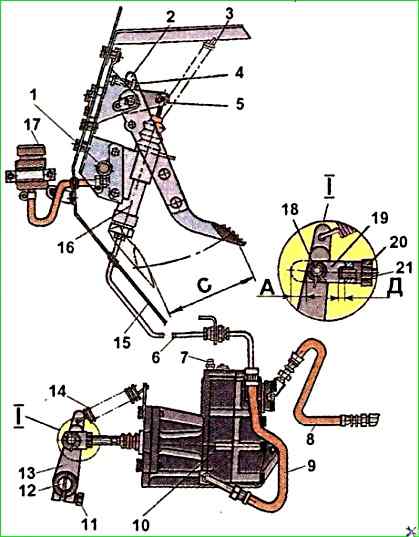
Clutch drive: 1 - lower pedal stop; 2 - pedal; 3 - release spring; 4 - movable stop (adjusting bolt); 5 - eccentric pin; 6 - hydraulic drive tube; 7 - bypass valve; 8 - air supply hose to the booster; 9 - hydraulic drive hose; 10 - pneumatic-hydraulic booster; 11 - tie bolt; 12 - clutch release fork; 13 - clutch release fork lever; 14 - spring; 15 - cab front shield; 16 - master cylinder; 17 - master cylinder reservoir; 18 - pin: 19 - pusher fork; 20 - lock nut; 21 - pusher; A - free travel of the pusher, corresponding to the free travel of the clutch release sleeve; C - full travel of the clutch pedal; D - the amount of the end of the pusher protruding from the threaded hole in the fork
To do this, do the following.
Unscrew the plug of the master cylinder reservoir, remove the plug reflector, then fill the system with working fluid to a level of at least 15-20 mm from the top edge of the reservoir.
The system should be filled with working fluid using a mesh filter to prevent foreign impurities from entering the system.
Remove the rubber cap from the bypass valve located in the upper part of the rear housing of the PGU and put the hose for bleeding the hydraulic drive on the valve head.
Lower the free end of the hose into the working fluid poured to 1/3 of the height of a transparent vessel with a capacity of about 0.5
Work is accelerated if there is a check valve at the end of the hose valve.
Unscrew the bypass valve by 1 turn and successively press the clutch pedal until it stops at the lower limiter of the pedal travel with intervals of 1-3 seconds between presses until the release of air bubbles from the working fluid flowing through the hose into the glass container stops.
When bleeding the system, ensure that the level of the working fluid in the master cylinder reservoir does not fall below 35 mm from the edge.
This will eliminate the possibility of air getting into the system and will allow the line to be replenished with working fluid.
Periodically top up the fluid if necessary.
With the clutch pedal pressed all the way down, tighten the bypass valve tightly. Then remove the hose from the valve head and put on the rubber cap.
The bleeding process can be somewhat accelerated if, after each press, without releasing the pedal, tighten the bypass valve and only then release the pedal.
Usually, after the third press, fluid without air bubbles begins to flow from the bypass valve.
After finishing bleeding the system, add fresh working fluid to the master cylinder reservoir to the level specified in point 1, install the plug deflector and tighten the reservoir plug.
Wipe the surface of the hydraulic drive parts.
Check the bleeding quality by the value of the full stroke of the PGU piston pusher, to do this, press the clutch pedal until it stops at the lower travel limiter.
With a correctly adjusted clutch control mechanism and a fully bled hydraulic system, the stroke of the PGU piston pusher should be equal to 27-28 mm.
The air pressure in the vehicle's pneumatic system must be at least 0.55 MPa.
At lower pressure, compressed air does not reach the pneumatic control unit and the force on the clutch pedal increases sharply, but the drive's performance is not lost.
If the pusher stroke is less than specified, and the system is in good working order and the clutch control mechanism is correctly adjusted, then continue bleeding, as indicated above, until the air is completely removed from the system and the proper of the pusher stroke.
The working fluid in the hydraulic system of the clutch control mechanism is Neva brake fluid, in the amount of 0.4 liters.
The use of other fluids is unacceptable, as it will lead to swelling of the rubber cuffs and seals and failure of the clutch control mechanism.
Care should be taken when handling brake fluid, as it is poisonous.
If brake fluid gets on the plastic lining of the heat and sound insulation in the cabin, it will destroy it.
Care should be taken when filling the brake system and clutch hydraulic drive with fluid.
If liquid gets on the plastic lining, remove the liquid immediately
")

")
")
")
")
")
")
")