Removal and inspection of springs of the ZIL-5301 vehicle
Dismantling the front and rear springs is carried out in the same sequence
To dismantle the springs from the vehicle, do the following:
- - loosen the tightening of the U-bolt nuts and the nuts of the spring hinge bolts;
- - disconnect the lower end of the shock absorber mount;
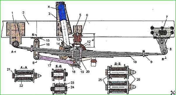
Front Suspension: 1 - Front bracket of front leaf spring; 2 - Vehicle frame; 3 - Shock absorber mounting bracket; 4 - Shock absorber; 5 - Compression buffer bracket; 6 - Compression buffer; 7 - Rear bracket of front leaf spring; 8 - Front leaf spring clevis; 9 - Spring clamp; 10 - Leaf spring; 11 - Spring U-bolts; 12 - Front leaf spring pad; 13 - Shock absorber mounting pin; 14 - Washer; 15 - Stabilizer mounting bracket; 16 - Stabilizer clevis cheek; 17 - Stabilizer; 18 - Stabilizer mounting cushion; 19 - Rod mounting bracket; 20 - U-bolt mounting nuts; 21, 24, 25 - Front spring to bracket mounting bolt; 22, 23 – spring mounting cushions; 26 - nut
- - lift the front part of the car with a jack to remove the front springs and the rear part to dismantle the rear springs so that the springs are unloaded;
- - place technological stands of the appropriate height under the frame of the raised part of the car and bus and lower the car;
- - unscrew the nuts of the spring hinge bolts, remove the bolts.
If it is difficult to dismantle the bolts, it is permissible to use a copper drift, but so as not to damage the threads of the bolts;
- - unscrew the nuts of the U-bolts and remove the U-bolts and spring lining;
- - lift the car with a jack so that the front end of the spring comes out of its bracket, and the rear end - out of the shackle, and remove spring.
To dismantle the front suspension stabilizer bar, unscrew the U-bolt nuts 19 (see Fig. 1) of the stabilizer mounting bracket and the pin mounting nuts 24, then remove the stabilizer bar.
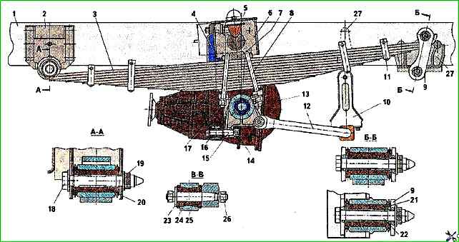
To dismantle the rear suspension stabilizer, unscrew the nuts 26 (see Fig. 2) fastening pins 24, then unscrew the stabilizer bar fastening nuts and remove the bar.
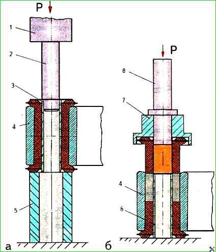
To disassemble the spring, it must be installed in the device (Fig. 3), clamped with a working screw, directing the clamping bracket towards the spring, or clamped with clamps, vices, etc. in the immediate vicinity of the center bolt.
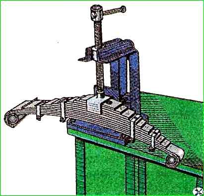
Unscrew the nuts of the clamp mounting bolts, remove the bolts with spacer bushings.
Unscrew the center bolt nut and carefully loosen the spring leaves, since the leaves are in a stressed state in the assembled spring.
The rear spring is disassembled in the same way.
Inspection
After disassembling, the spring leaves must be washed with MS-6 solution, wiped and carefully inspected.
When determining the condition of rubber-metal hinges, it is necessary to ensure that there is no separation of the rubber from the metal reinforcement, ruptures in the rubber mass, or cracks in the ends of the metal and plastic bushings.
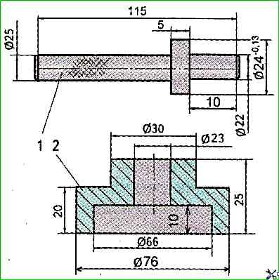
If the above defects are detected, they should be replaced (Fig. 4) by pressing them out of the spring eye using a special mandrel shown in Fig. 5.
Vehicles of different years of production may be equipped with rubber-metal bushings of different sizes with the same spring eye diameter of 44 mm.
Replacing bushings is only allowed in a set with a spacer talic bushing.
- Front and rear spring brackets that have cracks or breaks must be replaced.
Loose clamp rivets must be re-riveted.
Check the spring sheets for cracks using a magnifying glass or magnetic flaw detection.
If there are breaks or any cracks, the sheets should be replace.
If cracks or breaks are found in two or more leaf springs on the front suspension and three or more leaf springs on the rear suspension, the spring must be replaced entirely.
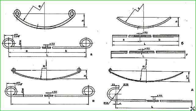
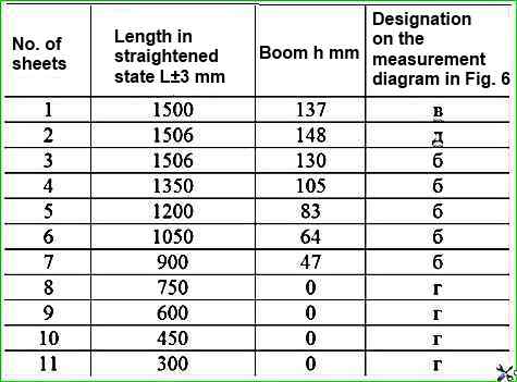
The dimensions of the leaf springs are given in Fig. 6 and in Tables 1 and 2.
Dimension "h" is given after shot blasting and spring settling.
Spring sheets are heat treated to a hardness of 363-444 HB.
All spring sheets are shot blasted from the concave side of the sheets, which significantly increases their fatigue strength.
Shot blasting is performed with shot of 1 mm in diameter, at a shot feed rate of 60 m/s, and a spring sheet feed rate of 1 m/min.
Parameters of the front spring sheets, (see Fig. 6)
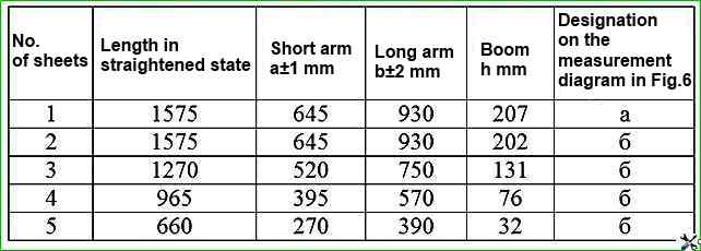
Parameters of the rear leaf spring of the car