To remove the longitudinal and transverse steering rods, you need to unpin the nuts securing the ball joints of the longitudinal rod to the pitman arm and the upper steering arm, remove the bolts from the pitman arm hole and disconnect the rod from the pitman arm
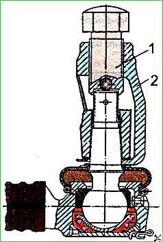
Then press out using the puller mod. And 804.29.00 (Fig. 1) ball joint from the upper steering arm.
Removing the transverse steering rods from the steering arms is done in the same way as removing the rear end of the longitudinal steering rod.
To disassemble the steering rods, they must be installed in a vice and securely fastened.
Unscrew the nuts securing the clamps and unscrew the steering rod ends traction.
The design of the steering rod joints is shown in Fig. 2.
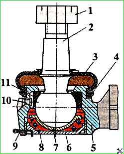
To disassemble the joint, remove the ring spring 4 securing the protective cover 3, then remove the cover without damaging it.
Unpin the threaded plug 6 of the joint by removing the cotter pin 9.
If the cotter pin cannot be removed, it should be bitten off.
Unscrew the threaded plug 6 from the tip 5 of the steering rod.
If it is difficult to unscrew the plug, moisten it with kerosene or brake fluid, remove the spring from the joint, the lower liner 7 with the ball pin 2, and remove the grease from the cavity of the joint.
To assemble the steering rods, screw the joint tip onto the steering rod pipe and tighten the nut of the clamp mounting tightening bolt.
When When screwing on, the tips must be located in the same plane.
Install the upper insert 11 (see Fig. 2) (the rivet head must enter the groove of the insert) and the ball pin 2 in the tip body, having previously lubricated the pin with Litol-24 grease.
Put Litol24 grease into the joint, install the lower insert 7 and spring 8.
Screw the threaded plug 6 into the rod tip body and cotter the plug with cotter pin 9.
The plug must be screwed in all the way, and then unscrewed to the first position for cotter pinning, but not less than 1/8 of a turn.
The torque required to rotate or swing the ball pin in the joint must be no more than 30 Nm.
Before measuring the torque, turn the ball pin by hand two or three times in both directions. Reuse of the cotter pin is not allowed.
Turn the rod in the vice with the ball pin facing up and install the rubber protective cover 3 on the end body and secure it with an annular spring.
Tighten the nut 1 by hand onto the ball pin.
Replace the rod in the vice and perform similar work for the second steering rod joint.
During vehicle maintenance, to lubricate the joint, unscrew the KG 1/8 plug in the rod ends, screw in the grease nipple and lubricate the joints until fresh grease is squeezed out from under the boot.
If the boot does not let the lubricant through during the process of replenishing the lubricant, then to prevent damage to the boot, lubrication should be stopped after the boot cavity is filled with lubricant, which is determined by the increase in its elasticity.
After lubrication, instead of the grease nipple, screw in plug.
Main parameters of steering drive parts
Ball pin. Steel 12ХН3А:
- Cracks on the surface, potholes or uneven wear of the surface under the tie bolt - must be rejected;
- Wear of the spherical surface 36.9-37.0 mm;
- Damage to the thread under the nut of the thread of the pin M20x1.5-6g mm - Reject if the threads are stripped;
- Wear of the neck under the pitman arm 26.062-26.039 mm - permissible without repair 26.01
Tie rod - Steel 20, pipe diameter 30x5.5 mm, GOST 8734-75, GOST 8733-87:
- Cracks or bends tie rods - reject;
- Damage to the tie rod thread under the tie rod end M24x1.5-7N - Reject if more than 3 threads are broken
Transverse steering rod. Steel 20, pipe with a diameter of 38x6 mm, GOST 8734-75, GOST 8733-74:
- Cracks or bends in the rod - reject;
- Damage to the tie rod thread under the tie rod end M30x1.5-7N-80 - Reject if more than 3 threads are broken
Steering rod ball joint bushings. Upper bushing - metal ceramics; lower - steel 08kp:
Cracks, chips, flaking on the surface of the upper liner - Reject;
Wear of the inner sphere of the upper liner:
- - larger diameter - 37.025-37.185 - Reject if wear of oil grooves;
- - smaller diameter - 30.14-30.42 - Reject if oil grooves are worn
Cracks, chips and pitting on the surface of the lower bearing - Reject
Damage to the spring of the ball joint - Reject
Damage or wear of the edges of the sealing boot - Reject
Threaded tip plug. Steel O8kp:
- Tearing off the edges of the grooves of the plug for the key - Reject
- Damage to the thread of the M56x1.5-6g plug. - Reject if more than 3 threads are torn
Tie rod ends. Steel 45, GOST 1050-88:
- Cracks and breakages - reject;
- Breakage or weakening of the upper liner retainer rivet - Replace the retainer rivet;
- Damage to the thread of the rod under the plug and under the rod pipe M56x1.5-6N - reject, M24x1.5-7N and M30xI.5-7N - reject if more than 3 threads are broken