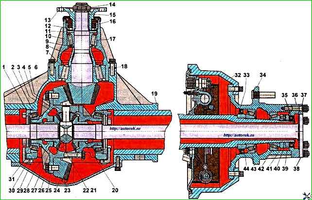
The final drive can be adjusted or repaired without removing the rear axle from the vehicle
The final drive bearing preload, lateral clearance in the engagement and contact patch are adjusted at the factory and, as a rule, they do not require adjustment during operation
They need to be adjusted only after the axle has been overhauled and parts have been replaced, as well as in case of significant bearing wear.
The plant produces a set of washers 2.65-3.15 mm thick with a thickness difference of 0.1 mm.
The bearing tension should not exceed 0.1 mm.
Adjustment must be performed as follows:
- - unscrew nut 14 without unlocking it. This must be done carefully so as not to damage the thread. It is recommended to lubricate the threads with oil.
First turn the nut at a small angle so as to only cut off the extrusion on the nut and return the nut to its original position, and then unscrew it completely;
- - unscrew the bolts securing the bearing cup to the axle housing and remove it from the housing together with the adjusting linings;
- - install the bearing cup on the press pads and press out the drive gear together with the inner bearing ring 7, adjusting washers 9 and spacer sleeve 8.
If there is no press, the same operation can be performed with a hammer using a soft mandrel;
- - remove the drive gear flange from the bearing cup;
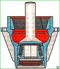
- - turn over the bearing cup and, using a mandrel installed on the inner race of the front bearing, press out the race with the cuff assembly (Fig. 2);
- - inspect the removed parts, replace the faulty ones if necessary;
- - the thickness of the newly installed adjusting washers should be less by the gap value (provided that the other parts have not been changed), and the gap value is rounded up to tenths mm;
To check the correct selection of washers, assemble the cup in the reverse order, without installing the cuff collar and installing the process flange without a mud deflector.
Tighten the flange nut (torque 400 ÷ 550 Nm), clamping the drive gear in a vice with soft metal gaskets, while turning the bearing cup so that the rollers take the correct position.
The correctness of the bearing preload is checked by the magnitude of the torque (Fig. 3) required to turn the drive gear without a seal and mud deflector. This value is 2.5÷4 Nm.
The torque measurement should be made with continuous rotation in one direction for at least five full revolutions of the shaft.
The bearings should be lubricated with the oil used for the main gear.
If the parts have been replaced, then two washers can be selected empirically so that after the trial assembly there is a small gap, measure it with an indicator, and then select the washers as described above.
After the final adjustment of the bearings, press the cuff housing together with the cuff into the cup, having previously placed consistent grease between the working edges of the cuff.
If the cuff was removed from the housing, then before installing it in the housing, it is recommended to lubricate its mounting surface with engine oil.
Tighten the drive gear flange fastening nut and lock it by pressing its edges into the groove on the gear shaft.
When tightening the nut, do not forget to rotate the pinion gear or bearing cup so that the bearing rollers take the correct position.
Steel adjusting linings 18 (see Fig. 1) must be lubricated with spindle oil or industrial I-30 before installing the bearing cup in the crankcase, and thin linings must be installed on both sides of the lining set.
The pinion bearing cup mounting bolts must be finally tightened to a torque of 70-100 Nm, while the pinion gear must rotate smoothly, without jamming.
Differential adjustment
Drain the oil through the drain hole;
Remove the crankcase cover;
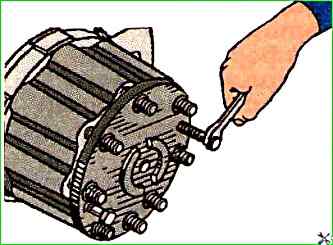
Unscrew the axle shaft mounting nuts to the hub, remove the spring washers and four expansion bushings from the studs.
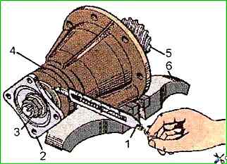
Screw two M10x1.5 bolts into the flange holes (Fig. 1), move it from its place, then manually remove the axle shaft, gasket and cuff housing together with the cuff.
In the same way, remove the other axle shaft;
Remove cotter pins 29 (see Fig. 2) from stoppers 30;
The lateral clearance in the engagement is measured with an indicator installed on the wide part of the tooth (Fig. 3).
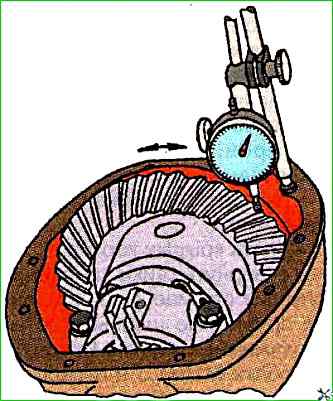
The clearance value should be 0.2-0.28 mm.
The final clearance check should be carried out after adjusting the bearing preload and the contact patch in the engagement;
To ensure the required preload in the differential bearings, first tighten the adjusting nuts uniformly until the axial clearance (without interference) in the bearings is eliminated, while turning the differential to correctly install the rollers in bearings.
If the adjusting nuts are difficult to turn, then the bearing cap bolts must be released and loosened.
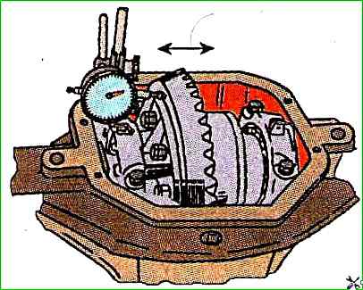
The axial clearance is measured with an indicator (Fig. 4);
To obtain the correct preload, the nuts on both sides are tightened by two notches from the zero clearance position.
After the final check of the lateral clearance in three evenly the adjusting nuts are locked on the located teeth.
Adjusting the contact patch in the main transmission gears
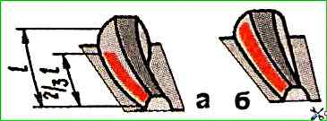
The position of the contact patch on the teeth of new gears with adjusted gear engagement should correspond to the contact patch shown in Fig. 1(a), and under load - in Fig. 1 (b).
The gap between the teeth must be maintained within 0.2÷0.28 mm for new gears and 0.5 mm (no more) for used ones.
After adjusting the driving and driven bevel gears, it is necessary to finally tighten the differential bearing cap mounting bolts.
The tightening torque should be 160÷200 Nm.
The gap between the teeth is measured with an indicator at the wide part of the tooth for at least three teeth of the driven gear, evenly spaced around the circumference.
For normal setting of the engagement of the gear teeth, a thin layer of oil paint should be applied to the working surfaces of several teeth of the driven bevel gear along the contact patch.
Then turn the shaft of the leading bevel gear in one direction and the other, braking the driven gear by hand.
The nature of the engagement of the gears is determined by the resulting contact patches.
The correct setting of the engagement of the gears is shown in the figure.
If the position of the patch is incorrect, normal engagement should be achieved by moving the leading and driven gears in the axial direction, proceeding in accordance with the table.
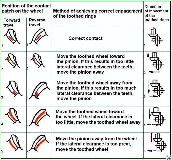
The leading bevel gear is moved by changing the thickness of the set of adjusting linings installed between the flanges of the bearing cup of the leading gear and the gearbox housing, the driven gear - by rotating the left and right adjusting nuts of the differential bearings by the same amount so as not to disturb the adjusted preload of the bearings.