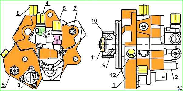
Diesel engines are equipped with high-pressure fuel pumps SR3.3 (Figure 1).
The high-pressure fuel pump (HPFP) is designed to create a fuel reserve, maintain and regulate the pressure in the fuel accumulator
The fuel priming pump 2, driven by shaft 9, and the electromagnetic pressure regulator 3 are mounted on the HPFP body.
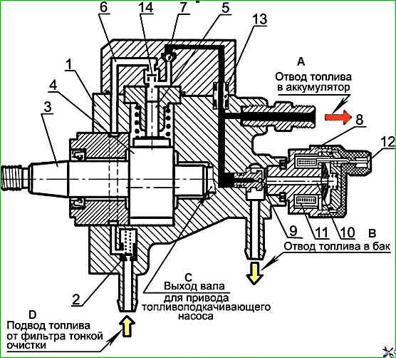
Three plungers 5 (Figure 2) are located radially in the HPFP body at an angle interval of 120°, and a cam rotor 4 is eccentrically mounted on the drive shaft 3 (the cams are located at 120° along the circumference of the rotor).
The drive shaft of the HPFP with a cam rotor has a gear drive from a reducer, the input shaft of which is in the drive half-coupling kinematic connection with the diesel crankshaft via timing gears.
Fuel, having passed through the coarse fuel filter with a moisture separator, is supplied under a pressure of 0.8-0.9 MPa by the fuel priming pump through the fine fuel filter to the inlet fitting of the high-pressure fuel pump.
Lubrication and cooling of the high-pressure fuel pump parts is carried out by diesel fuel supplied to the high-pressure fuel pump.
Under the influence of the created pumping pressure, safety valve 2 opens access for fuel through supply channel 6 into the above-plunger spaces.
The incoming cam of the rotor moves the plunger upward, while the inlet opening of the inlet channel is blocked and with further rise of the plunger, the fuel is compressed in the above-plunger space.
When the increasing pressure reaches a level corresponding to that maintained in the high-pressure accumulator, outlet valve 7 opens.
Compressed fuel enters the high-pressure circuit.
The plunger supplies fuel until it reaches TDC (delivery stroke).
Then the pressure drops, the outlet valve closes.
The plunger begins to move downwards. For one revolution of the shaft, each plunger (of three) makes one pumping stroke.
Since the high-pressure fuel pump is designed for a large feed rate, then at idle and at partial loads there is an excess of compressed fuel, which returns to the fuel tank through the pressure regulating valve 8 and the return drain line.
The pressure regulating valve sets the pressure in the high-pressure accumulator depending on the engine load, engine speed and thermal state.
If the pressure in the accumulator is too high, the valve opens and some of the fuel from the accumulator is diverted through the return drain line back to the fuel tank.
The pressure regulating valve is attached to the high-pressure fuel pump body via a flange.
Anchor 10 presses valve ball 9 to the seat under the action of the valve spring so as to separate the high and low pressure circuits.
The activated electromagnet 11 moves anchor, applying additional force to press the ball to the seat.
The entire anchor is washed with fuel, which lubricates the rubbing surfaces and removes excess heat.
")

")
")
")
")
")
")
")