To ensure normal operation of the diesel engine, observe the following requirements for servicing the lubrication system:
- - fill the oil sump with only the oil recommended by the manufacturer.
- - change the oil and oil filter in a timely manner, guided by the deadlines or according to the information of the electronic control system of the diesel engine with the corresponding blink code;
- - constantly monitor the oil pressure value on the pressure gauge located on the instrument panel (when the diesel engine is running at a nominal speed and a coolant temperature of 85-95 ° C, the oil pressure should be at the level of 0.25-0.35 MPa, the pressure value on an unheated engine up to 0.8 MPa is permissible);

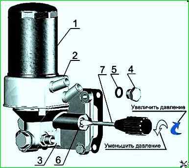
- - adjust the pressure value in accordance with Figure 1 as follows:
- - unscrew plug 4, remove gasket 5;
- - in the channel of the oil filter housing 3, use screwdriver 7 to turn the adjusting screw 6 one turn in the direction of increasing or decreasing the pressure value (depending on the actual pressure);
- - install gasket 5 and tighten plug 4;
- - if necessary, repeat the specified adjustment steps.
DO NOT adjust while the diesel engine is running.
Checking the oil level in the diesel crankcase
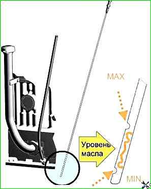
Check before starting the diesel engine using the oil dipstick located on the cylinder block diesel.
The oil level should be between the lower and upper marks on the oil dipstick in accordance with Figure 2.
The check should be done no earlier than 3-5 minutes after stopping the diesel engine, when the oil has completely drained into the crankcase.
It is prohibited to operate the diesel engine with the oil level in the crankcase below the lower and above the upper marks on the dipstick.

Changing the oil in the crankcase diesel
Change the oil in the diesel crankcase every 10 thousand km, and in cases of using duplicate oils or fuel with a high sulfur content - every 5 thousand km.
Drain the used oil only from a warmed-up diesel.
To drain the oil, unscrew the oil crankcase plug. After all the oil has drained from the crankcase, screw the plug back in place.
Pour oil into the diesel engine through the oil filler pipe up to the upper mark on the dipstick.
Pour only the oil recommended by this manual into the oil crankcase, corresponding to the period of operation.
Changing the oil filter

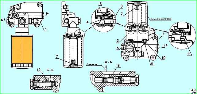
Change the oil filter every 10 thousand km or according to the results of diagnostics of the “COMMON RAIL” system in accordance with Figure 3 simultaneously with the oil change in the diesel crankcase in the following sequence:
- - unscrew the filter FM 009-1012005 or M5101 from the nipple 3, using a special key or other improvised means;
- - screw a new filter FM 009-1012005 or M5101 onto the nipple.
When installing the filter on the nipple, lubricate the gasket 4 with engine oil.
After the gasket touches the supporting surface of the filter housing 1, tighten the filter another 1-1.5 turns.
Installation filter on the housing only by hand.
Instead of the filter FM 009-1012005 and M5101, it is allowed to install non-separable filter cartridges: mod. X149 by AC Lelko (France), mod. L37198 by Purolator (Italy) and other companies that have an anti-drainage and bypass valve in their design with the following main dimensions:
- - diameter - 95-105 mm;
- - height - 140-160 mm;
- - thread - 3/4"-16UN


