Before assembly, all parts must be thoroughly washed and dried
Steering gear parts must not be wiped with napkins that leave threads and lint, which can clog the oil channels during operation of the mechanism.
During assembly, it is necessary to lubricate the parts with oil used for the power steering.
All rubber sealing parts must be replaced.
When assembling the steering gear, it is necessary to:
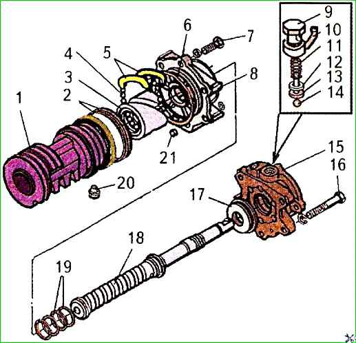
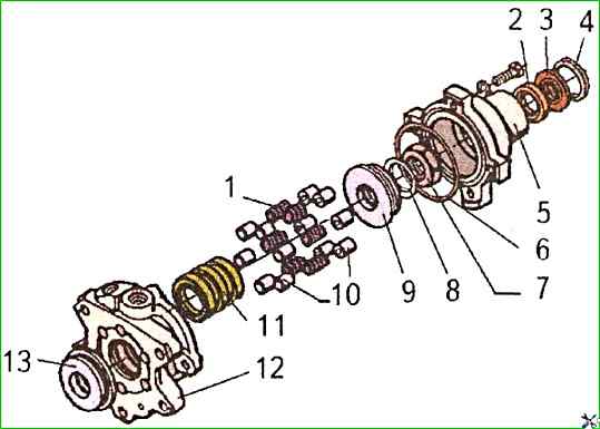
Put the sealing rings 19, intermediate cover 8 and ball nut 3 on screw 18 (Fig. 1).
Place ball nut 3 in a vice and insert screw 18 into the ball nut, aligning one of the holes in the nut, into which the grooves enter, with the screw groove of screw 18 for balls 4.
Insert twenty-three balls 4 through the hole in nut 3 facing the screw flange, turning the screw counterclockwise.
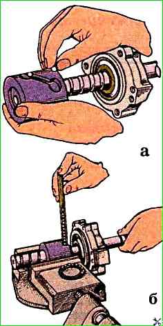
The balls can be placed manually or using a special tube (Fig. 2).
Place the remaining eight balls into the folded together grooves and prevent them from falling out by sealing the outlets with PVC or No. 158 grease.
It should be borne in mind that the balls are sorted into 14 groups at the manufacturing plant and all 23 balls must be from the same group.
Put the grooves with the balls into nut 3, turning screw 18 if necessary to to prevent the groove with the balls from falling out of the nut.
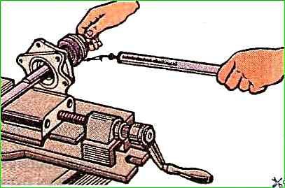
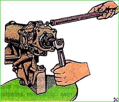
It is necessary to check the torque of the nut on the middle part of the steering screw using a dynamometer.
To do this, secure the end of the steering screw in a vice with soft metal jaws, wind a thin twine onto the ball nut, attach a dynamometer to the end of the twine and measure the torque of the nut (Fig. 3).
The torque of nut 3 should be 0.3-0.8 Nm in the middle part of screw 18, which will correspond to a force on the dynamometer of 9.3-25 N.
At the ends of screw 18, nut 3 should rotate freely, without force (loose fit).
When using a used kit, an axial clearance of no more than 0.2 mm is permissible.
In this case, the maximum torque should not exceed 0.8 Nm in the middle part of the screw and should decrease towards its ends.
If ball nut 3 on tail screw 18 rotates too tightly or too freely, it is necessary to replace balls 4 with balls of another group corresponding in diameter to the size.
The plant sorts balls by diameter into fourteen groups with a difference of 2 µm:
Group number - Ball diameter, mm:
- 7.158-7.156
- 7.156-7.154
- 7.154-7.152
- 7.152-7.150
- 7.150-7.148
- 7.148-7.146
- 7.146 -7.144
- 7,144-7,142
- 7,142-7,140
- 7,140-7,138
- 7,138-7,136
- 7,136-7134
- 7,134-7,132
- 7,132-7,130
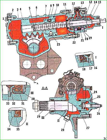
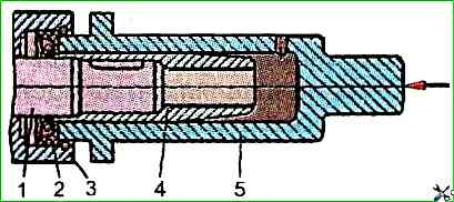
Insert piston-rack 4 (Fig. 4) into crankcase cylinder 3 and check the clearance between the cylinder wall and the piston. The gap should be 0.04÷011 mm.
Remove the rack-piston from the crankcase.
Insert the ball nut 7, aligning the threaded hole of the piston with the nut seats.

Tighten the set screws 23 and fasten the rack-piston with the ball nut using the device mod. And 803.03.300 (Fig. 5). Tightening torque - 50÷60 Nm.
Punch each screw 23 (see Fig. 4) in two places opposite the grooves in the piston-rack 4.
If the groove in the piston-rack coincides with the slot of the installation screw, the latter must be replaced.
Protrusion screw or extrusions above the cylindrical surface of the piston-rack is unacceptable.
Excessively protruding metal must be cleaned to prevent scoring of the crankcase cylinder 3.
Put 2 rings (rubber pressure ring and fluoroplastic ring) on the piston-rack using the model 2493 (Fig. 6) or mod. И 803.00.005
Install the model И 803.00.005 or model 2493 (Fig. 7) device on the rack-piston and, having compressed the rings, insert the rack-piston into the housing cylinder to the middle position
Remove the device and unscrew screw 6 (see Fig. 4) from the rack-piston by two revolution.
Make sure that the internal groove on the end of the spool valve 11 (Fig. 8) faces back towards the rear thrust bearing 9, and the chamfers on the reaction plungers 10 face outward.
Assemble the safety valve 14
The oil inlet nipple and the oil outlet elbow must have serviceable threads.
The spool valve, check valve, safety valve, and reaction plungers must move smoothly in the control valve body 15 without jamming or binding.
The spool valve, reaction plungers, and control valve body must not be disturbed during assembly, since they are individually selected.
Install the front thrust plunger on the steering screw 18 bearing 17, insert sealing rings 6 into grooves of intermediate cover 8.
Put control valve body assembly 15 onto steering screw, install rear thrust bearing 9 (see Fig. 8) and spring washer 8, placing it with concave side towards bearing, and washer protrusion should enter screw groove.
Tighten screw so that control valve body 12 aligns with intermediate cover with its end surface and centering groove; do not fully tighten adjusting nut. 7. This operation devalues centering of control valve body relative to steering screw;
After preliminary centering, screw 6 (see Fig. 4) of steering control must be unscrewed with special key mod. And 806.03.013 by one or two turns, while moving the valve body 19 away from the intermediate cover 11.
Tighten the adjusting nut 7, holding the steering screw from turning, as shown in Fig. 9.
Check the dynamometer rom torque of housing 19 (see Fig. 4) of the control valve.
The torque required for mutual rotation of the control valve housing and the steering screw must be within 0.6 ÷ 0.85 Nm, which will correspond to a force of 11 ÷ 15 N.
After adjusting the bearing tightening, lock the adjusting nut 14 by pressing its edge into the groove of the steering screw using the mandrel mod. И806.03.012.
Turning the screw, achieve abutment of the intermediate cover and the valve housing to the end of the steering gear housing, paying attention to the correct position of the two rubber sealing rings.
Screw in and tighten the housing and intermediate cover bolts, placing spring washers under the heads. The tightening torque of the bolts should be 35÷42 Nm.
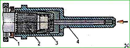
To press the cuff 2 (Fig. 10) into the socket of the upper cover 3, install it on the mandrel 4 and, having moved it to the cover 3 along the screw 1, press it into the socket using the mandrel 5 mod. And 806.03.004.
Insert the outer cuff 17 (see Fig. 4) into the socket and secure this unit with the retaining ring 16, installing it in the annular groove of the cover.
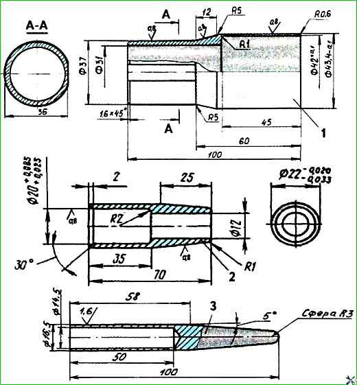
The dimensions of the mandrels for protecting the cuffs during assembly of the steering gear are shown in Fig. 11.
Insert the sealing ring 6 (see Fig. 8) into the annular groove of the split plane and install the cover 5 on the steering screw.
Secure the cover with bolts, placing spring washers under the bolt heads. Tightening torque of bolts - 21÷28 Nm.
Insert sealing ring 2 into the annular groove of lower cover 1 (see Fig. 4), installing the cover on the end split plane of the crankcase cylinder, screw in bolts with spring washers, secure the cover and bracket with bolts. Tightening torque of bolts - 35÷42 Nm.
Insert lower thrust washer 25, adjusting screw 26, upper adjusting washer into the socket of shaft 29 of the pitman arm and secure the unit with a retaining ring, inserting it with round-nose pliers into the annular groove of the shaft.
The axial movement of the adjusting screw relative to the pitman arm shaft (the gap between the thrust washers) should be within 0.02÷0.08 mm. The gap is adjusted by selecting adjusting washers.
Connect the pitman arm shaft to the side cover 24, screw the adjusting screw 26 into the threaded hole of the cover.
In this case, the pitman arm shaft should rotate freely by hand in the hole of the cover, and the adjusting screw should be stationary.
Screw a lock nut onto the screw, which should be tightened after adjusting the toothed engagement of the sector and the rack-piston.
Set the steering screw 6 to the neutral position, turning it with the key mod. And 806.03.013.
To do this, first turn the steering screw to the extreme forward position, and then turn it back two and a half turns (full screw travel is five turns).
Press the pitman arm shaft sleeve into the crankcase 3 (interference 0.075-0.175 mm) if it is replaced.
Install the pitman arm shaft 29 into the crankcase, guiding its splined end through the crankcase sleeve.
In this case, the teeth of the shaft sector must engage with the teeth of the rack 4 so that the middle tooth of the sector is located in the second depression from the front end of the piston-rack.
Install the thrust ring 30 in the bore of the steering gear housing.
Put mandrel 1 (Fig. 11) on the splines of the pitman arm shaft to protect the cuff from damage.
Lubricate the outer surface of the new cuff with oil and install it in the bore of the housing.
Press the cuff into the steering gear housing using mandrel 4 (Fig. 12) with light hammer blows until the mandrel flange rests against the end of the housing.
Put the outer seal 32 (Fig. 4) and the retaining ring 33 on the shaft.
Using mandrel 4 (see Fig. 12), finally press in the entire set of parts with light hammer blows until the retaining ring clicks into the groove.
Check whether the retaining ring has completely entered the groove of the steering gear housing.
Insert the sealing rings into the cover groove and secure the side cover 24 (see Fig. 4) with bolts, placing spring washers under the bolt heads. The tightening torque of the bolts is 35÷42 Nm.
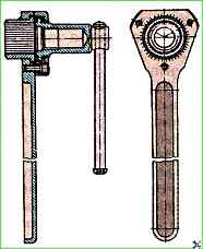
Check the rotation angle of the pitman arm shaft using a special lever key (Fig. 13) installed on the splined end of the shaft. The full rotation angle should be at least 90°.
Adjust the engagement of the sector and the rack piston 4 (see Fig. 4).
To do this, move the pitman arm shaft 29 in the axial direction with the adjusting screw 26, having first unscrewed the screw lock nut.
When screwing the adjusting screw into the housing of the side cover 24, the torque of the steering gear screw 6 increases, and when unscrewing it, it decreases.
The adjusting screw must be screwed in so that the gap in the gear engagement is within the range of rotation of the steering screw by half its turn in both directions.
The torque of the steering gear screw when passing through the middle position must be no more than 5 Nm.
After finishing adjusting the engagement of the teeth, secure the adjusting screw 26 with the lock nut, tightening torque - 40÷45 Nm.
Install the bipod on the splined end of the bipod shaft according to the marks, spring washer and tighten the bipod mounting nut.
")

")
")
")
")
")
")
")