Diagnostics, testing and maintenance of brakes ZIL-5301
Checking the brake systems on the stand
Checking the service brake system is carried out on a roller brake stand with the engine running
The equipped bus (car) with the driver is installed alternately with the front and rear axles on the rollers of the stand.
The rollers of the stand must not be oiled, the bus tires must be dry.
If the value of the resistance to rotation exceeds the data given in the table. 1, then you should check:
for the front wheels - the operation of the brake calipers;
for the rear wheels - the brake mechanisms.
Diagnostics of the condition and maintenance of the pneumatic drive of the brake system
Diagnostics of the condition and operability of the pneumatic drive devices can be determined by the readings of the control pressure gauge connected to the control terminals installed on the car (Fig. 1).
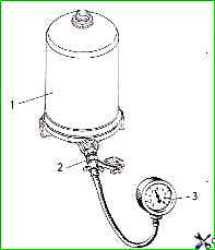
Diagnostics is performed by comparing the pressure gauge readings and the standards given in Table 1. It is recommended that this work be performed by qualified specialists.
Before testing, it is necessary to fill the pneumatic drive with compressed air until the compressor is switched off, i.e. until the moment the pneumatic drive pressure regulator is triggered, when the pressure in the system, monitored by the standard two-needle pressure gauge, stops growing.
Insufficient braking force indicates a malfunction of the brake system. In this case, it is necessary to eliminate the malfunction and repeat the test on the bench
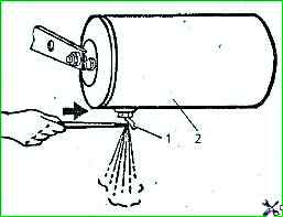
To ensure normal operation of the pneumatic brake drive system, it is necessary to open the drain valves in the air cylinders during maintenance and check for condensate (Fig. 2).
The presence of condensate in the cylinders is a sign of failure of the moisture-oil separator and the need to restore its operability.
When the moisture-oil separator is operating normally, there should be practically no condensate in the cylinders.
It is necessary to check the spring energy accumulator for leaks if there is compressed air in the circuit of the parking brake system drive. There should be no air leaks.
Before driving, make sure that the pressure in the system is not lower than 0.5 MPa.
While driving, the pressure in the pneumatic system of the brake drive should be within 0.65-0.80 MPa.
Only a short-term decrease in pressure is allowed during frequent repeated braking.
To avoid completely running out of air during frequent braking, do not stop the engine on long descents.
An increase in pressure in the system above 0.8 MPa indicates a malfunction of the pneumatic drive pressure regulator or unloading device, and above 1.35 MPa, in addition, indicates a malfunction of the pneumatic drive pressure regulator safety valve.
In this case, it is necessary to immediately eliminate the malfunction.
With the pedal in a free position with the engine not running, a decrease in pressure in the brake system by the pressure gauge scale reading should not exceed 0.05 MPa for 30 minutes and 0.05 MPa for 15 minutes with the controls on.
A rapid drop in pressure in the pneumatic system when the engine stops indicates an increased air leak from the system.
The location of a strong air leak from the system can be determined by ear.
A small leak can be determined using a soap emulsion.
Air leaks through connections are eliminated by tightening the connecting fittings.
If the brake valve drive is adjusted correctly, then the full travel of the service brake system pedal is determined by a ruler when pressing the pedal should be 105-115 mm.
When fully pressed, the pedal should not rest against the floor of the cabin.
Table 1
Front wheels:
- Resistance to wheel spin without braking, N - No more than 480;
- Brake force*, N - No less than 7840 at maximum pedal travel;
- Difference in brake forces on wheels of the same axle, % - No more than 20;
- Response time (time to reach maximum braking force when the brake pedal is pressed sharply), s 75% - No more than0.6
Rear wheels:
- Resistance to wheel rotation without braking, N - No more than 490;
- Brake force*, N - No less than 5880 at maximum pedal travel;
- Difference in brake forces on wheels of one axle, % - No more than 20;
- Response time (time to reach maximum braking force when sharply pressing the brake pedal), from 75% - No more than 0.6
The braking force should increase smoothly, proportionally to the force on the pedal.
Adjustment is carried out with two adjusting screws screwed into the pedal in the following sequence.
Loosen the roller axle mounting nut and the adjusting screw.
By turning the roller axis, ensure that when a force of 500-600 N is applied to the pedal, the gap between the floor and the pedal is at least 10 mm, and the air pressure in the two-cavity brake chamber is equal to the pressure in the air cylinders.
In this position, unscrew the adjusting screw 3 (Fig. 3) until it stops against the pedal bracket.
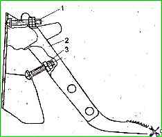
Turn the adjusting screw 1 until the gap between the roller and the pusher is no more than 0.3 mm when the pedal is released.
After this, secure the position of the roller axis and adjusting screws 1 and 3 with their nuts.
Diagnostics of the condition and maintenance of the hydraulic drive of the brake system
An important factor in the proper operation of the hydraulic brake drive is a thorough inspection of all pipelines and connections
- During the inspection, it is necessary to determine:
- the presence of dents and cracks on the pipelines, the appearance of which is not allowed;
- the presence of traces of contact of rubber hoses with mineral oils and lubricants that destroy rubber;
- the absence of swellings on the hoses that appear when pressing the brake pedal, in the presence of which the hoses must be replaced;
- the integrity of the pipeline fastening brackets;
- broken brackets must be replaced;
- no fluid leakage from the fittings. If there is any, tighten the nuts until they stop, preventing deformation of the pipelines.
If there is the slightest doubt about the operability of the drive parts, they must be replaced.
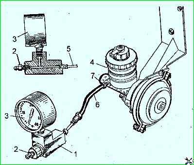
Checking the master brake cylinder. The performance of the master brake cylinder can be determined on the car using a special device shown in Fig. 4.
The reasons for failure of the master brake cylinder are:
- wear or loss of elasticity of the cuffs,
- wear of the working surfaces of the cylinder and pistons,
- swelling of the cuffs due to mineral oils entering the system,
- clogging of the compensation holes.
When the cuffs swell, as a rule, the car does not release the brakes due to the front cuffs blocking the compensation holes.
To determine this malfunction, it is enough to disconnect the tubes from the master brake cylinder.
If after the fluid has flowed out of the working cavities the leak stops and the level in the tank does not decrease, then the compensation holes are blocked by the cuffs or clogged.
Checking the pressure regulators hydraulic drive.
The pressure regulators are installed in the hydraulic drive to the rear brake mechanisms and are mounted on the frame side members at the rear of the vehicle.
The hydraulic drive pressure regulators do not require maintenance.
To check the regulators, do the following:
- unscrew the adjusting bolt from the pressure lever, having first unscrewed the lock nut;
- perform a test braking of the vehicle without a load on a dry horizontal section of the road with asphalt or concrete pavement.
- Brake at a speed of 50-60 km/h, smoothly increasing the force on the brake pedal until the wheels of one of the axles lock.
If during braking an advanced locking of the rear wheels is observed, then the regulators should be repaired or replaced.
Checking the hydraulic drive signaling device is carried out if there is a suspicion of its malfunction, installation of a new signaling device and each time the hydraulic drive is bled.
To check the correct operation of the signaling device, do the following:
- make sure the brake system malfunction indicator lamp is in good condition;
- remove the protective cap from the bleed valve of any front brake caliper and put a rubber hose on its head. Place the free end of the hose in a transparent container;
- unscrew the bleed valve by 1 turn;
- turn on the devices, fill the pneumatic drive system with compressed air;
- smoothly press the service brake pedal until it stops and screw in the valve. Release the pedal. When you press the pedal, the indicator should light up;
- with the bleed valves closed, press the brake pedal again. In this case, the indicator lamp should go out and not light up again when you press the pedal again;
- turn off the instruments;
- remove the hose from the bleed valve and wipe the valve thoroughly;
- put the protective cap on the valve head.
If the indicator lamp does not light up during the above operations, the indicator device must be repaired or replaced.
Check the brake fluid level monitoring device in the master cylinder reservoirs in the following order:
- turn on the instruments;
- check the serviceability of the brake system malfunction indicator lamp;
- press the float rods in the master cylinder reservoirs one by one, simulating a decrease in the fluid level.
If the lamp lights up, the device is in good working order
")

")
")
")
")
")
")
")