ZIL-5301 vehicles are equipped with a combined pneumatic-hydraulic brake drive with two independent hydraulic pneumatic circuits, divided into two circuits until July 2001, option 1 (Fig. 1a), and currently - option 2 (Fig. 1b)
AMO ZIL buses are equipped with a combined pneumatic-hydraulic brake drive with two independent hydraulic and pneumatic circuits and an ABS system.
At the request of customers, ABS is also installed on ZIL-5301 cars.
The bus brake drive diagram is shown in Fig. 2.
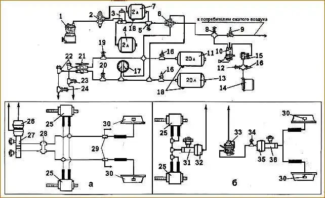
Diagram of the brake drive of the ZIL-5301 car: a - option for cars manufactured before July 2001; b - option with contours divided by bridges (since July 2001); 1 - compressor; 2 - pneumatic drive pressure regulator; 3 - moisture-oil separator; 4 - regeneration cylinder; 5.8, 12, 23, 24, 33 and 34 - control outlet valves; 6 - triple safety valve; 7 compensation cylinder; 9 - single safety valve; 10 - parking brake system valve; 11 and 13 - air cylinders; 14 – spring energy accumulator for the parking brake system drive; 15 - quick release valve; 16 - pneumoelectric pressure drop sensors; 17 - two-pointer pressure gauge of the working brake system; 18 - taps for draining condensate from air cylinders; 21 - two-section valve of the service brake system; 22 - brake signal switches; 25 - bracket with hydraulic cylinders for the front axle brake; 26 - two-cavity brake chamber; 27 - two-section master brake cylinder; 28 - signaling device; 29 - hydraulic pressure regulator; 30 - working hydraulic cylinders of the rear axle brake; 31 - main brake cylinder of the front axle; 32- front axle pneumatic chamber; 33 - pneumatic drive brake force regulator; 35 - pneumatic chamber of the rear axle wheels; 36 – master brake cylinder of the rear axle wheels.
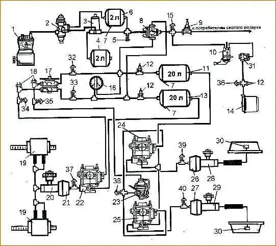
Diagram of the brake drive of a bus and ZIL-5301 vehicles with ABS: 1-compressor; 2 -pneumatic drive pressure regulator; 3 - moisture-oil separator; 4 - regeneration cylinder; 5, 15, 32, 33, 34, , 35, 36, 37, 38, 39 and 40 - control outlet valves; 6 - compensation cylinder; 7 - condensate drain taps; 8 - triple safety valve; 9 - single safety valve; 10 - parking brake system valve; 11 and 13 - air cylinders; 12 - pneumoelectric pressure drop sensors; 14 - spring energy accumulator for the parking brake system drive; 16 - two-pointer pressure gauge of the service brake system; 17 - two-section valve of the service brake system; 18 - brake signal switches; 19 - bracket with hydraulic cylinders for the front axle brake; 20 - main brake cylinder of the front axle; 21 - front axle pneumatic chamber; 22 - front axle modulator; 23 - brake force regulator; 24 - modulator of the right wheel of the rear axle; 25 - modulator of the left wheel of the rear axle; 26 - pneumatic chamber of the right wheel of the rear axle; 27 - pneumatic chamber of the right wheel of the rear axle; 28 - master brake cylinder of the right wheel of the rear axle; 29 - master brake cylinder of the left wheel of the rear axle; 30 - working hydraulic cylinders of the rear axle brake; 31 - quick release valve