Installing the connecting rod and piston group D-245
Check the conformity of the piston set size group and the cylinder liner size group
The pistons of one set on a diesel engine must be of the same size group corresponding to the cylinder liner size group
Size group "B"
Piston skirt diameter 110 -0.05-0.07 mm
Cylinder liner diameter 110 +0.06+0.04 mm
Gap between piston and liner 0.09-0.13 mm
Size group "C"
Piston skirt diameter 110 -0.07-0.09 mm
Cylinder liner diameter 110 +0.04+0.02 mm
Gap between piston and liner 0.09-0.13 mm
Size group "M"
Piston skirt diameter 110 -0.09-0.11 mm
Cylinder liner diameter 110 +0.02 mm
Gap between piston and liner 0.09-0.13 mm
Difference in weight of pistons of the same set should not exceed 10 g.
The difference in the mass of the connecting rods assembled with the pistons should not exceed 30 g.
Check that the size group of the connecting rod bearings corresponds to the repair or nominal size of the connecting rod journals.
The size groups of pistons and cylinder liners are given in the table.
Before installing the pistons assembled with the connecting rods and piston rings into the liners, wipe with a clean napkin and blow with compressed air the cylinder liners, the outer surface of the pistons, the working surface of the connecting rod bearing liners and the crankshaft journals.
The non-roundness and tolerance of the longitudinal section profile of the opening of the connecting rod upper head bushing is 0005 mm.
When pressing in the bushing, its symmetrical position relative to the midplane must be ensured connecting rod.
After boring, the surface of the upper head bushing hole should not have any scratches or burrs, the roughness of the machined surface should be Ra≤0.63 μm
One spiral or radial scratch with a width of no more than 0.1 mm is allowed on the upper surface of the bushing.
Cracks and scratches are not allowed on the surface of the connecting rod bolt. The bolt thread must be clean, without nicks or burrs.
The piston pin surface must be free of scratches, nicks or cracks.
The difference in the weight of the pins installed on one diesel engine must not exceed 10 g.
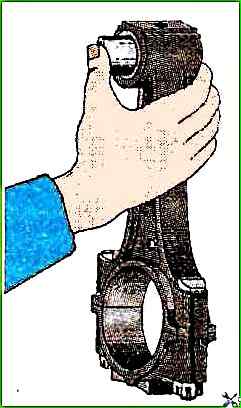
An unlubricated pin must easily rotate in the connecting rod with the force of the hand, must not have transverse swing and must not fall out of the connecting rod under the action of its own weight.
The radial clearance (gap) between the piston ring and the control gauge for the upper compression ring should not exceed 0.02 mm over no more than 10% of the surface and no closer than 20° from the lock; and for oil scraper rings, the ovality should be within 0.15-0.65 mm
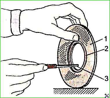
The gap in the joint of the rings should be within 0.3-0.6 mm, and adjusting this gap is not allowed.
The tensile strength of the rings when bending the ring is at least 441 Nm.
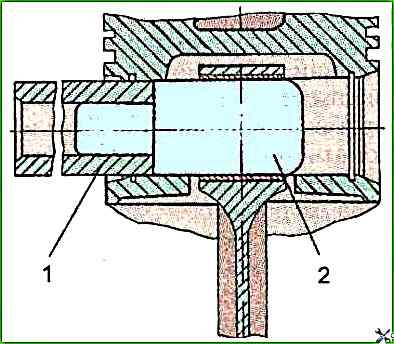
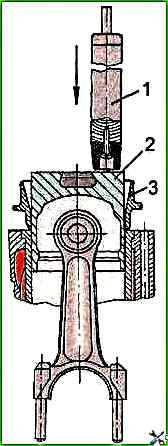
It is recommended to assemble the connecting rod with the piston and pin using a special mandrel, shown in Figure 3.
Each piston is equipped with an upper compression ring, coated with chrome on the outer surface, two (or one) compression cone rings and one box-type oil scraper ring with a spring expander.
The compression cone rings on the end surface at the lock have a marking top, which should face the piston bottom when installing the rings
The joint of the oil scraper ring expander should not coincide with the ring lock.
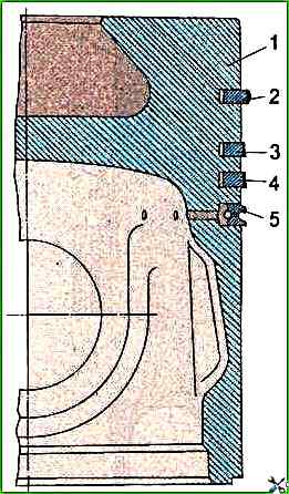
Oil scraper piston rings are installed with a mark (press-out) applied to the surface of the ring 7-20 mm from the lock, to the piston bottom.
When the piston rotates in a horizontal position, the piston rings should move freely, without jamming , move in its grooves and sink into them under the action of their own weight.
Piston ring locks must be located at an equal distance around the circumference.
The cylinder liner mirror, pistons with piston rings, crankshaft connecting rod journals and connecting rod journal liners must be lubricated with engine oil.
The locks of adjacent piston rings must be located at an angle of 180°.
To install pistons in the block sleeve, use mandrels I 806.01.200 and I 804.01.200.
The tightening torque of the connecting rod bolt nuts should be within 180-200 Nm.
The axial play of the lower connecting rod heads on the connecting rod journals is allowed to be no more than 1 mm at any position of the crankshaft.
For a new diesel engine, the axial play is within 0.15-0.4 mm.
The crankshaft turning torque after tightening all the connecting rod bolt nuts should not exceed 60 Nm.
At TDC, the plane of the bottom of each piston should protrude above the upper plane of the cylinder block by 0.3-0.55 mm.
The gap between the piston head and the sleeve at a distance of 3 mm from the upper plane of the block should be at least 0.2 mm.
")

")
")
")
")
")
")
")