Synchronization of the crankshaft and fuel injection pump drive gearbox shaft pulse wheels D-245E3
The need to install (reinstall) the crankshaft and fuel injection pump drive gearbox shaft pulse wheels for their synchronization may be caused by dismantling the fuel injection pump drive gearbox during routine repairs of the diesel engine
The installation of pulse wheels according to the proposed scheme is carried out to synchronize the signals of the crankshaft and primary fuel injection pump drive speed sensors and is ensured by linking the sensor signals to a common reference point of the shaft position at the moment the piston of the first cylinder passes the top dead center (TDC).
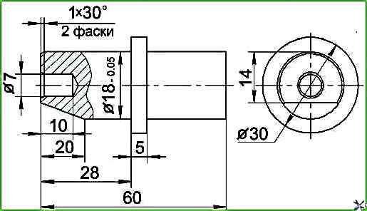
To ensure the correct installation of pulse wheels, it is necessary to make a device for fixing the installation pin of the gearbox toothed wheel in accordance with the sketch (Figure 1).
Remove the cylinder head cover cap.
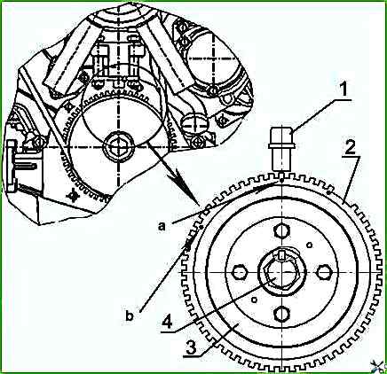
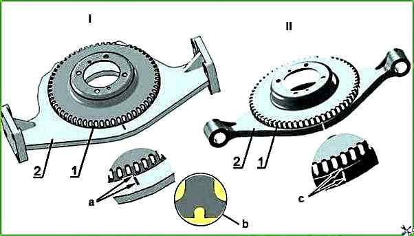
Set the piston of the first cylinder to the TDC position by turning the crankshaft clockwise, using bolt 4 (Figures 4a, 4b), until they coincide (depending on the design of the impulse wheel):
- a) - the gap in the "crown" of the pulse wheel is made in the form of a segment of depressions;
- b) - the gap in the "crown" of the pulse wheel is made in the form of a solid segment):
- - a) the axis of the 16th tooth of the "crown" of the pulse wheel (when counting counterclockwise from the segment of the gap in the "crown" of the pulse wheel) with the axis of sensor 1 Figure 4a;
- - b) the axis of the 16th depression of the "crown" of the pulse wheel (when counting counterclockwise from the segment of the gap in the "crown" of the pulse wheel) with the axis of sensor 1, Figure 4b;
Make sure that the intake and exhaust valves of the 1st cylinder are closed, if the exhaust valve is open, turn the crankshaft a full revolution and recheck the condition of the valves.
Set the piston of the first cylinder on the compression stroke (≈ 60° of the crankshaft rotation angle before TDC), for which:
c) for diesel engines with a crankshaft position lock:
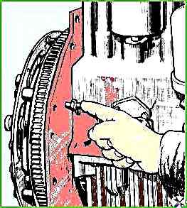
- turn the crankshaft clockwise using bolt 4 (Figures 4a, 4b) approximately two turns, while on the second turn, unscrew the lock from the threaded hole of the rear sheet in accordance with Figure 2, insert it with the back side into the same hole until it stops in the flywheel and turn the crankshaft until the lock coincides with the hole in the flywheel;
In this case, impulse wheel 2 (Figures 4a, 4b), fixed on crankshaft pulley 3 will be positioned in such a way that the axis of sensor 1 will pass along the axis of the sixth tooth of the "crown" (design - a), or along the axis of the sixth depression of the "crown" (design - b), of the impulse wheel (counting counterclockwise from the segment of the gap in the "crown" of the pulse wheel).
d) for diesel engines without a crankshaft position lock:
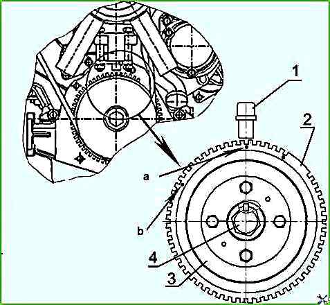
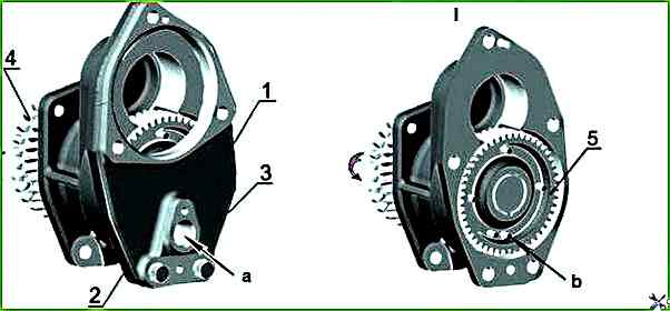
- turn the crankshaft clockwise, using yi bolt 4 (Figures 4a, 4b) approximately two turns, while on the second turn turn the crankshaft until the timing marks on the pulse wheel 1 (Figures 3a, 3b) and the front support 2 coincide.
In this case, the pulse wheel 2 (Figures 4a, 4b), secured to the crankshaft pulley 3, will be positioned in such a way that the axis of the sensor 1 will pass along the axis of the sixth tooth of the "crown"
- (design version - a), or along the axis of the sixth depression of the "crown"
- (design version - b), of the pulse wheel (when counting counterclockwise from the segment of the gap in the "crown" of the pulse wheel).
On the removed gearbox, turning the drive half coupling 5 (Figure 7) clockwise (in Figure 5 the gearbox is shown with the gearbox drive gear installed on the drive half-coupling) achieve the appearance of two successively located pulse pins in the window for installing the sensor.
By slightly turning the drive in the opposite direction, position the installation pin (the first one in the direction of shaft rotation) in the center of the window (see Figure 5).
Install the device for fixing the position of the installation pin 1 (Figure 6) in the window for installing the frequency sensor of the gearbox shaft (Figure 5).
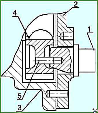
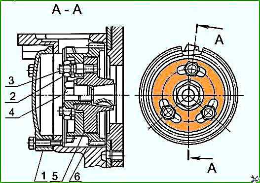
Remove hatch cover 1 (Figure 7) and, supporting drive gear 6 through the hatch window, insert studs 3 of drive half coupling 5 into the drive gear grooves, thus installing the gearbox.
Fasten the gearbox on the distribution board.
Install and tighten nuts 2 to a torque of 35-50 Nm.
Remove the installation tool.
Reinstall the gearbox shaft speed sensor, hatch cover and secure them.
Remove the flywheel lock (on engines with a crankshaft position lock) and screw it with the threaded part into the rear sheet.
Install the cylinder head cover cap.