Disassembling the ZIL-5301 pneumatic hydraulic booster
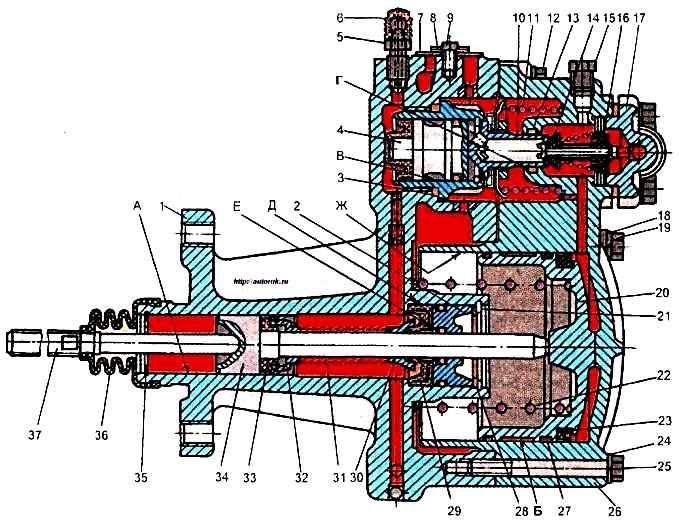
Disassembling the pneumatic hydraulic booster (PGU) for repairs is usually done in the following cases: fluid leaks through cuffs 29, 33, due to their swelling when using low-quality fluids; when the cuff of the pneumatic piston 23 wears out.
The probability of failure of other parts is small
Disassembly procedure
Remove cover 36 with pusher 37 from the PGU.
Secure the PGU in a vice, directing the front housing 26 upwards.
Unscrew connecting bolts 12 (2 pcs.), 19 and 25 (5 pcs.).
The last bolt to unscrew is the one located in the gearbox area.
In this case, hold housing 26, since springs 11 and 22 act on it.
Remove housing 26, springs 11 and 22, diaphragm 10 assembled with the seat.
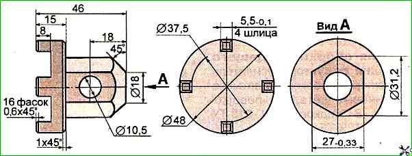
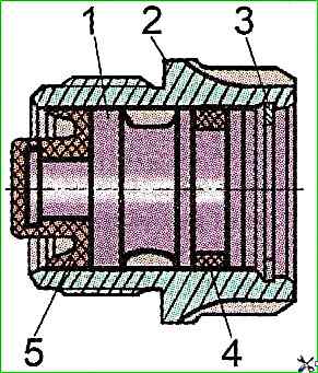
Using a special key (Fig.↑ ) unscrew the housing of the follower piston of the gearbox 4 from the rear housing 1 (see Fig.1).
Remove the rear housing 1 of the amplifier from the vice.
Remove the retaining ring 35 and remove the clutch release piston 34 from the rear housing as an assembly, pushing it out by the protruding rod on the side of the seal 2.
Remove the spacer sleeve 30, spring from the piston rod 34 31, bushing 32 and cuff 33.
Remove retaining ring 21 of clutch release piston rod seal and washer 28.
Press cuff 29 and seal 2 of clutch release piston rod out of rear housing.
Remove piston seals 1 and 3 from housing 2.
On housing 1 (see Fig. 1), unscrew and remove bypass valve 5 complete with cap.
Unscrew screws 9 securing cover 8 of outlet hole, remove cover and seal 7 of outlet hole.
It is not necessary to perform the last two operations.
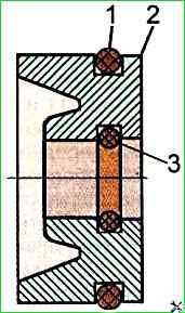
To disassemble the diaphragm of the amplifier reducer, it is necessary to unlock nut 3 of the diaphragm of the reducer and unscrew it.
Remove washer 2, diaphragm 1, washer 6 and gasket 5 from seat 4 of the diaphragm. This unit should not be disassembled unless necessary.
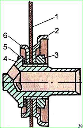
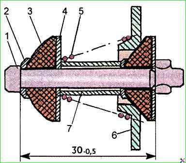
To disassemble the follower piston of the power steering reducer, remove the sealing ring 3 from the follower piston housing (see Fig. 1).
Remove the follower piston 1 from the housing 2 (Fig. 4) together with the cuff and the sealing ring.
Remove the sealing ring 4 and the cuff 5 from the piston 1.
Remove thrust ring 3 from housing 2 of the follower piston.
To disassemble the front housing of the amplifier and the pneumatic piston, it is necessary to remove the sealing ring 13 (Fig. 1) of the reducer diaphragm seat from the front housing, the pneumatic piston 20 of the amplifier in assembly.
Remove cuff 23 and guide rings 27 from the pneumatic piston 20.
Fasten front housing 26 in a vice, pointing the air supply cover 17 upwards.
Unscrew the cover fastening bolts (4 pcs.), remove the cover and take out the power steering reducer valve 14, removing the adjusting and sealing aluminum gaskets 16 from both sides of the seat of this valve.
The power steering reducer valve is of a non-separable design; if necessary, it is replaced as an assembly.
Wash the clutch booster parts and assemblies in MS-6, MS-V TU 6-15-978-76 solution, blow them with compressed air.