Assembly and adjustment of the ZIL-5301 pneumatic hydraulic booster
Assembly of the PGU is carried out in the reverse order of disassembly.
Lubricate the rubber seals of the piston rod and the surface (see Fig. 1) with NG-213 TU 38.101.129-75 liquid.
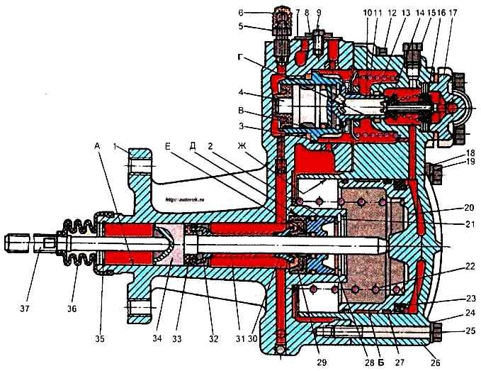
Press seal 29 into rear housing 1 using a mandrel.
Install seal 2, having first assembled it with sealing rings 1 and 3
install washer 28 and retaining ring 21.
To assemble the clutch release piston (see Fig. 1), lubricate all rubber parts and surfaces with brake fluid before assembly.
Install seal 33, spacer sleeve 32, spring 31, spacer sleeve 30 on clutch release piston rod 34.
Insert the assembled unit into housing cylinder 1 and install retaining ring 35.
Install seal 7 of outlet opening, cover 8 and tighten cover fastening screws 9.
Install and tighten bypass valve 5 complete with cap 6.
To assemble the follower piston of the power steering reducer, before assembly lubricate all rubber parts and the surface with brake fluid.
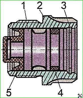
Then install the sealing ring 4 and cuff 5 on piston 1 (see Fig. 4); install the follower piston 1 assembly into housing 2; install thrust ring 3 into body 2 of follower piston and put sealing ring 3 on body of follower piston (see Fig. 1).
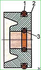
To assemble reducer diaphragm, install two gaskets 5, washer 6, two diaphragms 1 and washer 2 on seat 4 (Fig. 5), tighten nut 3 to torque of 20-25 Nm and lock by punching at one point.
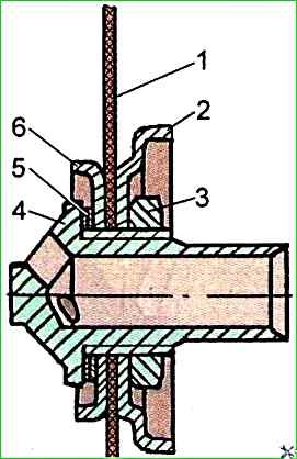
To assemble the front housing of the amplifier and the pneumatic piston, it is necessary to install the cuff 23 and guide rings 27 on the pneumatic piston 20 (see Fig. 1).
Then install the pneumatic piston 20 in assembly into the front housing of the amplifier.
Before installing it, fill the cavity "B" and lubricate the surface "G" with a thin layer of grease 158TU 38.101.320-77.
Install a new sealing ring 13 of the reducer diaphragm seat into the front housing of the amplifier.
After subassembling the assemblies of the pneumohydraulic amplifier, it is necessary to install the rear housing 1 of the amplifier in a vice with the connector facing up.
Tighten the housing of the follower piston of the reducer in assembly into the rear housing of the amplifier. with a special key.
Place the amplifier reducer diaphragm 10 assembled with the seat on the rear amplifier housing, the surface of which should be lubricated with a thin layer of grease 158 TU-38.101.320-77, and align its holes with the holes for the mounting bolts in the rear amplifier housing.
Insert extension rods (diameter 6 mm, length 100 mm) into these holes.
Install the diaphragm spring 11 of the gearbox and the spring of the pneumatic piston 22.
Install the front housing of the amplifier 26 as an assembly on the rear housing 1, directing the holes for the fastening bolts along the guide rods.
Press on the front housing and compress the springs until the gap between the housings is eliminated, and the diaphragm seat should enter the hole in the front housing where the sealing ring 13 is located.
It is unacceptable for the seat to rest rigidly against the housing (especially with a noticeable increase in the compression force)
Without releasing the front housing, remove one guide rod, insert bolt 19 with a spring washer and screw it in completely, but do not tighten it and, alternately removing the guide rods, insert and screw in bolts 12, 19 (Second) and 25 with spring washers.
Then tighten the bolts evenly to the end.
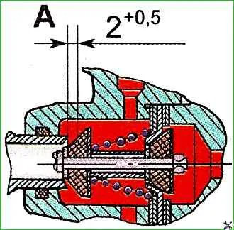
Install the power steering reducer valve 14 in assembly into the front housing of the amplifier, adjusting the gap (Fig. 6).
Gap "A" (seat travel before contact with the valve) should be 2+0.5 mm.
It should be adjusted using shims 16 (see Fig. 1), which should be installed at least one on each side of the seat.
The gap size is determined as follows:
Measure the movement of the diaphragm seat, which is the difference in the distances from the end of the seat to the end of the front housing in the initial position and after the seat has completely moved when creating pressure in the hydraulic system of the PGU to overcome the resistance of the compressed spring of the reducer 11
Install valve 14 with one shim under the seat and press it tightly in the seat using a tubular sleeve with a mounting flange;
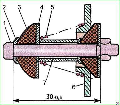
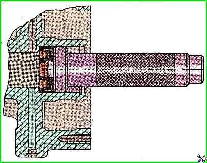
- measure the displacement of the valve stem 1 (Fig. 7), which is the difference in the distances from the end of the valve stem to the end of the tubular pressure sleeve in the initial position and after the valve stem has fully moved when creating pressure in the hydraulic system of the PGU.
The pressure in the hydraulic system can be created using compressed air of 0.5 ÷ 0.6 MPa, supplied through the hole for connecting the hydraulic hose, after tightening the bypass valve.
The difference between the displacement of the diaphragm seat and the displacement of the valve stem will be the gap between the diaphragm seat and the outlet valve.
If this value is less than the specified one, then adjusting linings (the thickness of one lining is 0.5 mm) are placed under the valve seat until the required value is obtained gap.
It is best to move the diaphragm seat and valve stem with a depth gauge.
Install the air supply cover 17 (Fig. 1) on the front housing of the amplifier and tighten the bolts that secure it.
There should be a uniform gap of 0.5-1 mm around the entire perimeter between the front housing and the cover to ensure that the cover is pressed firmly against the valve seat and that it is tight. If this requirement is not met, an air leak occurs.
After assembly, it is necessary to check the tightness of the air and hydraulic parts of the PGU.
To check the tightness of the air part of the PGU, it is necessary to connect a one-liter tank equipped with a pressure gauge and an inlet shut-off valve to the air supply cover 17.
Compressed air with a pressure of 0.5 ÷ 0.7 MPa is supplied to the tank inlet.
First, the inlet part is checked, which is the volume under the air supply cover, the seal of the end of the cover with the valve seat 14 and the seal of the rear cone (inlet) valve and the valve seat. To do this, the inlet valve of the liter tank is closed and the pressure drop is measured.
The tightness is considered satisfactory if the pressure in the tank drops by no more than 0.05 MPa in 30 seconds.
Then the working air part is checked, which additionally includes the seal of the front cone (outlet) valve and the reducer diaphragm seat, the seal of the pneumatic piston cuff between the piston itself and the wall of the cylinder of the front housing, the seal of the diaphragm between the front and rear housings, as well as the tightness of the front housing and the pneumatic piston themselves.
To do this, a pressure of 0.5-0.7 MPa is created in the pneumatic system of the PGU, the inlet valve of the liter tank is closed and the pressure drop is measured.
The tightness is considered satisfactory if the pressure in the tank drops by no more than 0.05 MPa.
To check the tightness of the hydraulic part, it is necessary it is necessary to install a pressure gauge between the PGU and the main cylinder.
Then the system is bled to remove air from it.
The hose is disconnected from the compressed air supply cover. A pressure of 6.5-7.0 MPa is created in the hydraulic system.
The main cylinder is locked and there are no leaks through it.
The tightness is considered satisfactory if the pressure in the pipeline drops by no more than 0.05 MPa in 30 seconds.
")

")
")
")
")
")
")
")