Installing the rear sheet, cuff housing and flywheel of the D-245 crankshaft
The rear sheet should fit tightly on the pins pressed into the cylinder block
The rear sheet and the mating plane with the crankcase, as well as the surface of the flywheel and crankshaft flange should be wiped with a clean napkin.
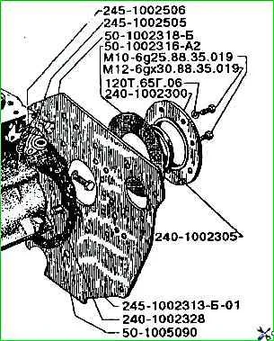
The paronite gaskets of the rear sheet and the cuff body must be lubricated with UZOM paste on both sides before installing them on the pins.
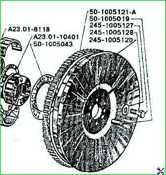
Flywheel
Cracks and chipping of the working surface of the flywheel ring gear teeth are not allowed.
Reduction in the length of the ring gear teeth (excluding the chamfer length) is allowed up to 16 mm (the length of the teeth of the new ring gear is 18 mm).
Wear of the flywheel ring gear teeth is allowed up to a thickness of 3.2 mm with a height of installation of the vernier tooth gauge of 2.4 mm (the thickness of the tooth of the new ring gear corresponds to 4.73 mm).
Before pressing, the flywheel ring gear must be heated to a temperature of 195÷200°С.
The flywheel and ring gear seats must be free of nicks and burrs. A gap of no more than 0.5 mm in one place on an arc of no more than 60° is allowed in the mating surface between the ring gear and the flywheel.
The flywheel with the ring gear must be dynamically balanced as an assembly with a pre-balanced crankshaft by drilling radial holes.
Residual imbalance at each end of the shaft is no more than 350 g mm.
After balancing, depersonalization of parts is not allowed.
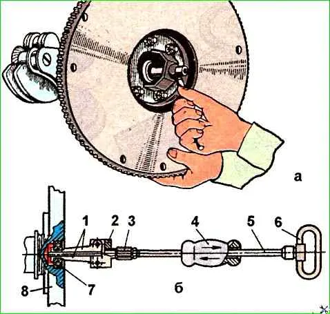
If it is necessary to replace the front bearing of the primary shaft of the gearbox, then before removing the flywheel from the shaft, it should be pressed out using a screw puller mod. И 8О3.16.000 (Fig. 2a) or, after removing the flywheel, press out the bearing using an impact puller mod. 2476 (Fig. 2b).
After installing the grips on the ends of the bearing rings, they are moved apart by the threaded stop 3, and then, when the load hits the shaft stop 5, the bearing is pressed out.
The flywheel surface mating with the clutch driven disk surface is ground.
The surface roughness should be no lower than Ra≤1.0.
The mating surfaces of the flywheel and crankshaft flange should not have nicks, burrs or other damage.
The flywheel mounting bolts should be tightened evenly in several steps, the final tightening of the flywheel mounting bolts should be carried out with a torque of 180-200 Nm.
The flywheel should be installed very carefully, tightening the bolts crosswise.
After preliminary tightening, make sure that there is no gap between the flywheel and the crankshaft.
There were cases when the flywheel was installed at an angle.
In this case, the flywheel mounting bolts are cut off.
")

")
")
")
")
")
")
")