Before starting work, the car should be cleaned of dirt and washed.
To remove the front axle from the car, you need to lift the car and install stands under the front axle beam, unscrew the wheel mounting nuts and remove them.
Loosen the clamps of the flexible hoses supplying fluid to the brake working cylinders and disconnect these hoses.
Unscrew the nut securing the lower end of the shock absorber and remove the bushing and washer, disconnect the lower end of the shock absorber.
Disconnect the end of the longitudinal steering rod from the pitman arm.
Unscrew the nuts securing the front springs to the frame bracket and remove the spring eye pins.
Disconnect the anti-roll bar mounts.
Disconnect the front suspension from the car and bus frame or from the front axle beam axles.
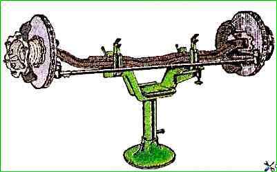
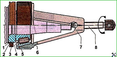
Lift the car, remove the front axle from the supports and install it on the stand mod. 2173 for disassembling and assembling the front axle (Fig. 1).
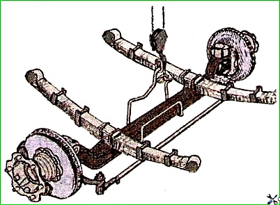
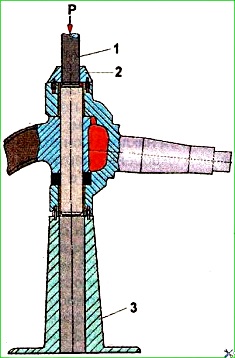
The axle mooring method is shown in Fig. 2.
The front axle is disassembled in the following sequence
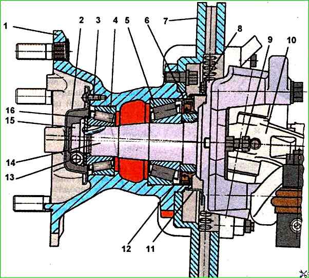
Unscrew the three screws securing cover 2 (see Fig. 3) and remove it together with the gasket.
Unscrew bolt 13 and adjusting nut 15, remove thrust washer 16.
Bend back the brake caliper mounting lock plate, unscrew the two caliper mounting bolts and remove it from the brake disc together with the hose bracket.
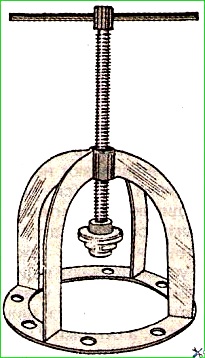
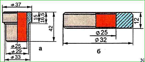
Install the puller (Fig. 4) and remove the hub with the brake disc assembly.
In this case, the outer bearing 4 (see Fig. 3) and the outer ring of the inner bearing 5 are also pressed off.
Press off the inner bearing 4 using a special puller (Fig. 5).
Unscrew bolts 8 (see Fig. 3) securing mudguard 11 and remove it.
Remove (if necessary) the cuff ring from the steering knuckle.
The cuff support ring should be pressed off only if there is wear or cavities on the ring surface.
Disconnect the transverse and longitudinal steering rods.
Unscrew the bolts securing the steering knuckle arms and remove them.
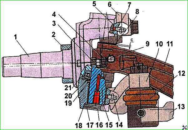
To remove the steering knuckle 1 (Fig. 6), remove the thrust rings 18 with round-nose pliers and take out the upper and lower covers 16 with the sealing rings 17.
Unscrew the kingpin fastening wedge nut, knock out the wedge with a hammer and a copper mandrel.
Then press out the kingpin using a special device for this purpose.
Install the device so that the axes of the mandrel 2 (Fig. 7) and the kingpin coincide, press out the kingpin, remove the steering knuckle 1 (see Fig. 6), adjusting linings 8, thrust bearing 20 together with the cup 21. Remove the sealing rings 19.
Press out the bushings from the steering knuckle using a mandrel (Fig. 8 and 9).
To remove the second steering knuckle, perform the same operations.
")

")
")
")
")
")
")
")