Assembly of the 4UTNI-T-1111005-50 high-pressure fuel pump for the ZIL-5301 vehicle
Before assembly, the low-pressure cavity of the pump must be flushed with diesel fuel under a pressure of 1.8-2.0 MPa. filtered M10G2 motor oil should be used to lubricate the pump and regulator parts
Plunger pairs and discharge valves should be thoroughly washed with filtered diesel fuel.
When assembling plunger rotary bushings with plunger pairs, the plunger should move freely in the grooves of the rotary bushing, without jamming or seizure.
When installing a plunger rotary bushing in a pump assembled with a gear ring, the head of the gear ring screw should face the middle of the hatch.
In this case, the gap in the ring slot should be at least 0.5 mm with the gear ring screw tightened.
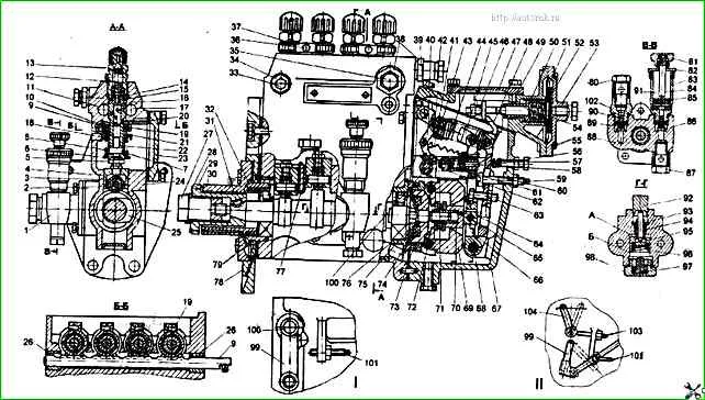
High-pressure fuel pump: I - single-lever injection pump variant; II - double-lever injection pump variant; 1 - fuel priming pump; 2 - tappet roller sleeve; 3 - tappet roller; 4 - plunger tappet; 5 - tappet adjusting bolt with lock nut; 6 - lower plate; 7 - plunger tail; 8 - plunger spring; 9 - rack; 10 - toothed ring; 11 - fuel outlet channel; 12 - delivery valve spring; 13 - nipple; 14 - delivery valve; 15 - gasket; 16 - delivery valve seat; 17 - fuel supply channel; 18 - plunger sleeve; 19 - tightening screw; 20 - pin; 21 - upper plate; 22 - plunger rotary sleeve; 23 - cover; 24 - fuel injection pump housing; 25 - camshaft; 26 - rack nut; 27 - nut; 28 - washer; 29 - splined sleeve; 30 - mounting flange; 31 - key; 32 - spring; 33 - enrichener plug; 34 - bushing; 35 - bypass valve; 36 - bolt; 37 - clamp; 38 and 102 - bushings; 39 - boost corrector housing; 40 - spring lever; 41 - starting enrichener spring; 42 - finger; 43 - earring; 44 - governor spring; 45 - rack rod; 46 - stop; 47 - boost corrector cover; 48 - main governor lever; 49 - pin; 50 - bushing; 51 - diaphragm; 52 - plate; 53 - boost corrector cover; 54 - rod; 55 - screw; 56 - bolt; 57 - idle spring; 58 - corrector rod; 59 - adjusting linings; 60 - rigid stop; 61 - corrector housing; 62 - bracket; 63 - bolt; 64 - heel; 65 - intermediate lever axis; 66 - intermediate lever; 67 - speed regulator housing; 68 - lever axis; 69 - weight; 70 - governor coupling; 71 - adjusting screw; 72 - weight axis; 73 - hub; 74 - elastic drive with rubber elements; 75 - thrust washer; 76 - bearing cup; 77 - plate retainer; 78 - pump mounting plate; 79 - bearing; 80 - square bolt; 81 - handle-nut; 82 - cover; 83 - vertical cylinder; 84 - rod; 85 - fuel priming pump piston; 86 - nylon lowering valve; 87 - rotary square; 88 - housing; 89 and 96 - springs; 90 - discharge valve; 91 - fuel priming pump; 92 - pusher; 93 - guide sleeve; 94 - rod; 95 - fuel priming pump piston; 97 - stop; 98 - plug; 99 - fuel supply control lever; 100 - control lever shaft; 101 - maximum speed adjustment screw; 103 - engine stop lever adjustment screw; 104 – diesel stop lever
The plunger rotary bushing installed in the pump, together with the toothed rim, with the toothed rim screw tightened, must rotate freely on the plunger bushing; jamming is not allowed.
When assembling the lower plates of the pusher springs with the plungers, the plunger tail with its cylindrical surface with a diameter of 6.2 mm must freely pass through the slot in the plate, the support heel of the plunger tail must recess into the groove of the plate with a diameter of 11.5 +0.27 mm.
When assembling pushers 4 (see Fig. 1), the roller axis must rotate freely in the holes of the pusher housing, the pusher roller must rotate freely on the bushing, and the bushing on the axis roller.
Seizures in the mating of the specified parts are not allowed.
The pushers, pre-lubricated with clean engine oil, should move easily, without jamming or seizures, under the action of their own weight in the housing bores.
When installing the rack in the pump housing, the guide bushings and rack must be lubricated with clean engine oil.
The movement of the rack in the pump housing must be easy and smooth, jamming is not allowed.
When installing the plunger rotary bushings assembled with the toothed rims, the slots of the toothed rims must be installed perpendicular to the side surfaces of the pump.
In this case, the distance from the inner side of the rack pin to the pump housing must be 16 ± 0.5 mm.
After installing the pins that secure the plunger bushings, the mobility should be checked slats.
The slats should move easily, without feeling jamming. Sharp, jerky movements of the rack are not allowed.
After installing the discharge valves in the pump body, a gasket with the conical surface facing up must be installed on the seats of the discharge valves.
The fuel pump fittings must be tightened to a torque of 98-108 Nm, having previously lubricated them with filtered diesel fuel or oil.
After installing the springs, pushers and lower plates, it is necessary to check for:
- - absence of pinching of the plunger tail between the pusher bolt and the lower plate of the plunger;
- - smooth movement of the rack;
- - ensuring the above-plunger clearance at the extreme upper position of the pusher, which must be at least 0.3 mm.
Before installation, the camshaft bearings must be lubricated with engine oil.
The bearings must be pressed onto the 20 mm diameter camshaft journal until they stop; any distortions are unacceptable.
Before installing the camshaft into the pump housing, the condition of the bearing rings and separators must be checked.
Damage to the separators and loss of rollers are not allowed.
The nut the camshaft must be tightened to a torque of 43 Nm and locked with a lock washer.
Dents from the crimping device are allowed on the bent surfaces of the lock washer, but burrs are not allowed.
After installing the camshaft in the pump housing, measure the axial force applied to the shaft from the regulator side.
When moving the camshaft from 0.02 to 0.1 mm, it must be at least 450 N.
With a further increase in the load on the camshaft, an additional movement of at least 0.5 mm must be ensured.
If the force is less than 442 N, the required number of adjusting shims must be installed under the outer ring of the bearing in the bearing cup.
Installing one adjusting shim increases the axial force by 24.5-29 N.
The value of the axial force on the camshaft is measured in the absence of a load on the camshaft from the tappets.
It is permissible to measure the axial force on the camshaft with the tappets lowered.
In this case, the minimum axial force applied to the shaft must be at least 638 N.
It is strictly forbidden to hit the camshaft nut, the camshaft tail from the regulator side or the bearing cup with a hammer when adjusting the axial force.
When adjusting the axial force on the camshaft, it is necessary to ensure that there is a gap between the fuel pump housing and the second and third cams of the camshaft.
The gap must be ensured by installing adjusting linings in the bearing cup or by shifting them from the bearing cup to the mounting flange.
The two upper bolts of the mounting plate must be installed on the anaerobic sealant UG-11.
")

")
")
")
")
")
")
")