ZIL-5301 Parking Brake System Spring Accumulator
The parking brake system drive uses a spring accumulator (Fig. 1) designed to activate the rear wheel brakes when the parking brake system is engaged
A strong spring is compressed in the cylinder, so if the spring accumulator is disassembled incorrectly or carelessly, you can get injured.
To disassemble the spring accumulator, it must be removed from the bracket by disconnecting the air supply pipe.
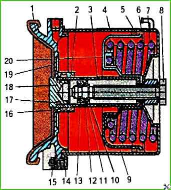
Install and secure the energy accumulator in a vice with soft jaws by flange 1 with pusher 18 upwards and remove rubber cover 19.
Heat pusher 18 to a temperature of 200 °C and unscrew it with a special socket wrench.
Put air under a pressure of at least 0.5 MPa into the energy accumulator.
Insert a special split mandrel model И 804.00.008 into pipe 3 and, having seated bearing 12 downwards with it, remove thrust ring 13.
Remove the energy accumulator from the vice and, having turned the cover with the flange downwards, remove thrust ring 13 of the bearing, bearing 12 and ring 10.
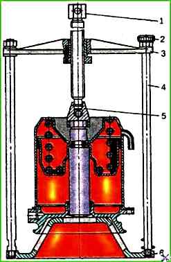
For further disassembly of the energy accumulator, it must be installed in a special device model И 804.33.000 (Fig. 2) and use screw 1 to compress the power spring 7 (see Fig. 2).
Then unscrew bolts 14 with an open-end wrench, holding nuts 15 with another wrench.
After this, carefully unscrew the screw of the device and remove cylinder 4, spring 7, piston 9 and, if necessary, unscrew screw 8.
It is strictly forbidden to unscrew bolts 14 securing the cylinder of the energy accumulator outside the device.
After disassembling the brake spring energy accumulator parts, wash them with clean gasoline or acetone, dry them and carefully inspect them.
On the surface The body parts must not have any cracks, hairlines or other defects visible to the eye.
The parts must be cleaned of rust and burnt-on deposits. All rubber parts must be replaced.
To assemble the spring energy accumulator, install flange 1 on a special device and insert piston 9 into it with tube 3 down.
Then install power spring 7 with a tapering loop towards the piston, centering the spring on spring plate 20 so that the ground part of the spring is in the sector of the plate that has internal and external flanges, and cover it with cylinder 4 so that the drain pipe branch pipe is in the middle between the bosses of flange 1.
Compress spring 7 with the screw of the device and secure cylinder 4 to the flange with bolts 14 and nuts 15.
Unscrew the screw of the device, remove the energy accumulator from it and secure it in a vice by flange 1.
Turn over the energy accumulator in a vice at 180° and supply it with air under a pressure of at least 0.5 MPa.
Install ring 11 in tube 3, pressing it with mandrel И804.00.008, needle bearing 12, thrust ring 13, orienting it with the chamfer upward, and thrust ring 11.
Release air from the energy accumulator and unscrew and screw in the release screw 8, observing at the same time whether the tube 3 is fed, i.e. the correct installation of the thrust ring 13.
After normal release of the brakes is ensured, screw in the screw 8 again and tighten it to a torque of 40-50 Nm;
Re-supply air under a pressure of at least 0.5 MPa to the energy accumulator, visually check the correct installation of the thrust ring 13, put the rubber sealing ring 17 on the pusher 18, apply a drop of anaerobic sealant to its thread and screw the pusher 18 to a torque of 40-50 Nm into the tube 8.
Remove excess sealant with a napkin.
Put the protective cover 19 on the flange 1 and the pusher 18.
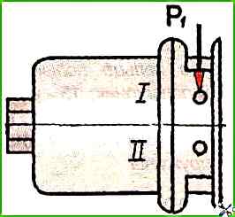
To check the spring energy accumulator after assembly, install it on the stand and connect it to the diagram shown in Fig. 3.
In this case, the release screw 8 (see Fig. ↑ 1) must be screwed in until it stops.
Feed and release three times air under pressure of 0.75 MPa into output 1. Check the stroke of the pusher.
To check the cut-off pressure of the spring energy accumulator, it is necessary to reduce the pressure in output 1 to 0.48-0.54 MPa. In this case, the pusher can move no more than 5 mm
The tightness of the spring energy accumulator is checked by soaping the joints and by the absence of air leakage from the drain pipe in the static position of the pusher (the handle of the parking brake valve is in the "drive" position).
")

")
")
")
")
")
")
")