Assembly and installation of the ZIL-5301 gearbox
Assembly and installation of the intermediate shaft
Install key 8 in the shaft grooves and sequentially press the second gear pinion (0.005-0.055 mm interference), reverse gear (fit from 0.04 mm interference to 0.01 mm clearance), third and fourth gear pinions (0.015-0.065 mm interference), pre-selected by journals, onto the shaft.
Install the spacer sleeve, press on the constant mesh gear (0.015-0.065 mm interference) and secure it with a lock ring. Install the ring using a mandrel.
All intermediate shaft gears must be pressed on until they stop against the end face.
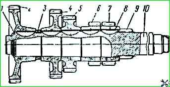
Intermediate shaft of the gearbox, assembled: 1 - lock ring; 2 - constant mesh gear; 3 - spacer sleeve; 4 - fourth gear gear; 5 - third gear gear; 6 - rear axle gear; 7 - second gear gear, 8 - key; 9 - first gear ring gear; 10 - shaft
Install the gearbox housing on the fixture
Insert the intermediate shaft front roller bearing ring into the housing socket (fit from 0.01 mm interference to 0.033 mm clearance).
Put the roller bearing on the front end of the intermediate shaft (gap 0.015-0.047 mm).
Insert the intermediate shaft with gears into the crankcase, sequentially first guiding the rear end of the shaft into the ball bearing seat, then install the front end of the shaft with the roller bearing assembly into the outer ring.
Press the ball bearing assembly with the lock ring onto the rear end of the intermediate shaft (interference 0.003-0.032 mm), guide it into the crankcase seat, install the bearing together with the shaft into the crankcase seat using a special mandrel (fit from interference 0.012 mm to gap 0.038 mm).
Screw on the nut and tighten it. Tightening torque not less than 250 Nm.
Secure the nut by pressing its thin edge into the groove of the shaft. Install the rear cover with the gasket and secure the cover with bolts and spring washers.
Install the retaining ring in the groove of the front bearing housing and seat it using a mandrel, insert the plug into the socket and press it in using a special mandrel.
Insert the roller bearings into the hole of the reverse gear block, installing a spacer spring between them, install the block in the gear housing, insert the gear block axle (with fit: the end of the large diameter axle - from an interference of 0.052 mm to a gap of 0.004 mm, the end of the smaller diameter axle - with a gap of 0.007-0.060 mm).
Install the locking plate in the groove and secure it with a bolt and spring washer.
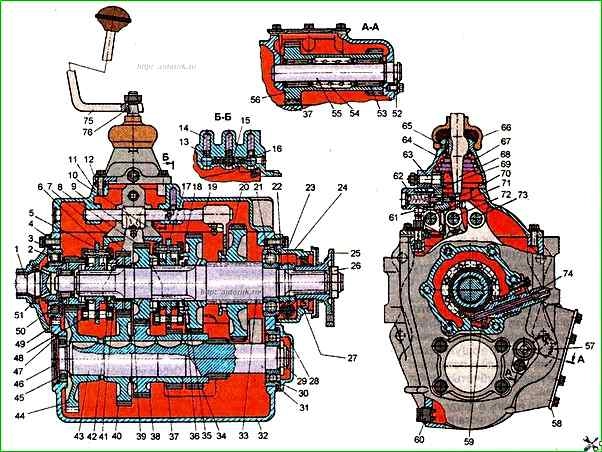
Gearbox: 1 - primary shaft; 2, 21,30 and 45 - bearings; 3, 28, 31 and 47 - retaining rings; 4 - primary shaft rear bearing cap; 5 - fourth and fifth gear synchronizer; 6 - fourth gear pinion sleeve; 7 and 40 - fourth gear gear pair; 8 and 38 - third gear gear pair; 9 - first gear and reverse gear shift rod head; 10 - second and third gear shift fork; 11 - gearbox cover; 12 - mounting sleeve, 13 - detent ball; 14 - detent spring, 15 - pin of the locking device of the gearshift rods; 16 - locking device ball, 17 - synchronizer of the second and third gears; 18 and 34 - second gear toothed pair; 19, - first gear shift fork and reverse gear; 20 - first gear and reverse gear toothed wheel, 22 - speedometer drive worm; 23 and 59 - speedometer drive gears; 24 - secondary shaft bearing cover; 25 - flange with reflector; 26 - secondary shaft flange nut; 27 and 51 - cuffs; 29 - intermediate shaft nut; 32 - gearbox housing; 33 - secondary shaft; 35, 39 and 41 - thrust washers; 36 and 42 - lock rings, 37 - intermediate shaft reverse gear wheel; 43 - intermediate shaft; 44 - constant mesh pinion; 46 - plug; 48 - gasket; 49 - locking pin, 50 and 53 - roller bearings; 52 - lock plate; 54 and 67 - springs; 55 - reverse gear wheel block axle; 56 - reverse gear wheel block; 57 - check filler plug; 58 - power take-off hatch cover, 60 - drain plug with magnet; 61 - breather; 62 - first gear and reverse gear disengagement fuse; 63 - intermediate lever axle; 64 - gearshift lever tip housing; 65 - lever lock; 66 - gear shift lever boot; 68 - gear shift lever tip; 69 - intermediate lever; 70 - intermediate lever cracker; 71 - first gear and reverse gear shift rod, 72 - fourth and fifth gear shift rod; 73 - second and third gear shift rod; 74 - speedometer drive shaft nipple; 75 - gear shift lever
Assembly and installation of the secondary shaft and synchronizers
Place the shaft in a vice with soft pads with the rear end down and assemble the shaft parts in the sequence indicated below.
Put gear 12 of the first gear onto the splines, install gear 11 of the second gear, put thrust washer 10 on the shaft, secure the gears with locking ring 9, fitting it into the groove of the shaft using a special mandrel.
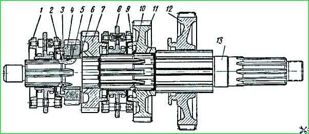
Assembled secondary shaft: 1 - fourth and fifth gear synchronizer; 2 and 9 - lock rings; 3, 6 and 10 - thrust washers, 4 - fourth gear pinion, 5 - fourth gear pinion sleeve; 7 - third gear pinion; 8 - second and third gear synchronizer; 11 - second gear pinion; 12 - first gear pinion; 13 - secondary shaft, gear block, two roller bearings and spacer sleeve
Install the synchronizer 8 of the second and third gears on the shaft splines, install the gear 7 of the third gear on the shaft journal, having installed the thrust washer 6, install the sleeve 5 of the gear of the fourth gear, having directed its locking pin into the spline groove of the shaft.
Install the gear of the fourth gear on the sleeve, install the thrust washer 3 and secure the gear with the locking ring 2, having seated it in the groove of the shaft using a hollow mandrel.
The ring should fit tightly in the groove.
Install the synchronizer of the fourth and fifth gears on the shaft splines.
Install the secondary shaft assembly in the crankcase gearbox, directing the rear end of the shaft into the crankcase seat, put the bearing assembly with the locking ring on the end of the shaft and, directing it into the crankcase seat, press the bearing together with the shaft using a special mandrel.
Assembly and installation of the primary shaft
To assemble the primary shaft, install it in the fixture and press the bearing (interference 0.003-0.038 mm).
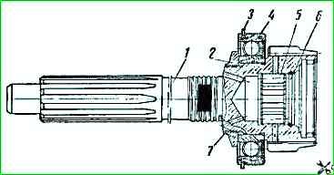
Assembled primary shaft: 1 - shaft; 2 - lock rings; 3 - retaining ring; 4 - ball bearing; 5 - roller bearing
Install locking rings 2 into the grooves. Remove the shaft from the fixture and install the roller bearing into the socket.
Install the primary shaft with the bearing assembly into the crankcase socket (bearing fit from interference of 0.012 mm to clearance of 0.038 mm) and direct the end of the secondary shaft into the roller bearing of the primary shaft.
Install the primary shaft bearing cover with a gasket, secure them with bolts and spring washers.
Put the coupling with the clutch release bearing on the cover guide and install the release spring on the coupling.
Assembling the gearbox cover
Assembly of the gearbox cover is performed in the reverse order disassembly.
When assembling the cover, first insert rod 11 with the fork for shifting first gear and reverse, then rod 10 with the fork for shifting fourth and fifth gears, and finally rod 9 with the fork for shifting second and third gears.
After installing the rods and forks, they should be secured with lock bolts 14, cotter pinned with wire, wrapping its ends as shown in Fig. 5-7 (pos. 8, 13 and 15).
Check and, if necessary, set the first gear pinion and synchronizer carriages to neutral position.
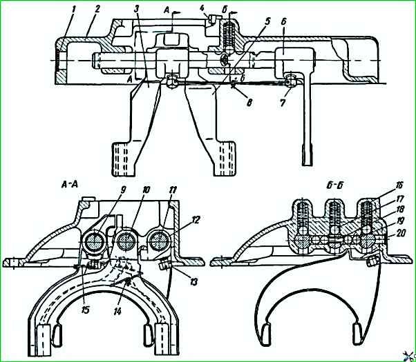
Gearbox cover assembly: 1 and 20 - plugs; 2 - cover, 3 - fourth and fifth gear fork; 4 - mounting sleeve; 5 - second and third gear fork; 6 - first gear and reverse fork; 7 - breather; 8, 13 and 15 - cotter pin wire; 9 - second and third gear shift fork rod; 10 - fourth and fifth gear shift fork rod, 11 - first gear and reverse gear shift fork rod; 12 - first gear and reverse gear shift fork rod head; 14 - lock bolts, 16 - retainer spring, 17 - retainer ball; 18 - rod lock pin, 19 - rod lock ball
Install the gearbox cover with the gasket, guiding the ends of the fork into the first gear pinion groove and the grooves of the other fork legs on the synchronizer carriage disks, then secure the cover with bolts and spring washers.
Assembly of the gear shift lever tip housing
Fix the gear shift lever tip housing in a vice by inserting the lock 7 of the lever into the housing hole, install the gear shift lever 10, apply a little grease to the ball surface of the lever, put the support 6 of the ball part of the lever on the lever tailpiece, install the spring 5 of the lever, turn the bent end as shown in the figure, and put the spring behind the housing projections.
Assemble the intermediate lever 2 by installing the cracker 1 and the axle 4 in it, lubricating them with grease.
Install the lever together with the axle in the housing, then secure it in the housing with the nut 3 and spring washer.
Remove the housing from the vice, install the protective cover 9, screw the ball handle 12 onto the gear shift lever and secure it with the nut 11.
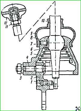
Gear shift lever tip housing unit: 1 - intermediate lever cracker; 2 - intermediate first and reverse gear engagement lever, 3 - axle nut; 4 - lever axle; 5 - lever spring; 6 - lever support; 7 - lever lock; 8 - lever housing; 9 - protective cover, 10 - gear shift lever tip
Install the housing 8 of the lever tip with the gasket, directing the end of the intermediate lever into the slot of the first gear and reverse gear rod head, and the end of the gear shift lever tip into the groove of the gear shift fork, secure the lever housing with bolts and spring washers.
Install the speedometer drive pinion on the end of the secondary shaft.
Install the secondary shaft cover and secure with bolts and spring washers.
Install the flange with the reflector on the splines, place the thrust washer on the shaft, screw on the nut and tighten it; tightening torque - not less than 300 Nm.
Lock the nut by pressing the thin edge into the groove of the secondary shaft.
Install the nipple with the driven gear of the speedometer into the secondary shaft cover. Fasten the nipple with a bolt and washer.
It is recommended to install all cover gaskets on a sealant.
Install the gearshift lever with a key on the tip and fasten with a nut and a spring washer.
Testing the gearbox
After assembly, it is necessary to fill the gearbox with oil up to the level of the control plug and check it on a special stand.
The gearbox should be run in from an electric motor for 3-5 minutes, on each sequentially engaged gear.
During the gearbox run-in, check for normal gear engagement, the absence of increased gear noise in engagement and knocks, the absence of oil leaks in the cuffs and joints, as well as the absence of other malfunctions.
Install the serviceable gearbox on the engine using a jack-trolley or hoist with the cabin ventilation hatch removed, secure the gearbox gears on studs with nuts and spring washers. The tightening torque of the nuts should be 120-150 Nm.
")

")
")
")
")
")
")
")