The ABS modulator is designed to control the air supply to the pneumatic chambers of the main cylinders
The front axle wheel modulator is mounted on the front panel of the cabin, the rear wheel modulators are on the frame brackets near the rear axle
Disassembling and assembling the ABS modulator
Install the modulator in a vice with soft jaws with the atmospheric outlet 23 (Fig. 1) facing up and clamp it by the housing 20.
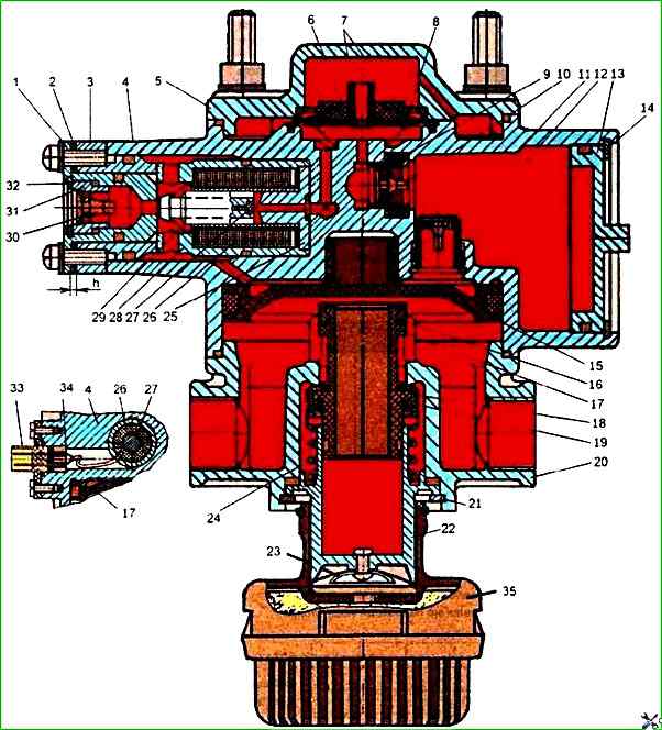
Use round-nose pliers to remove thrust ring 21 and remove guide cap 22, spring 24 and valve body 17 with valves 16 and 18 from the housing.
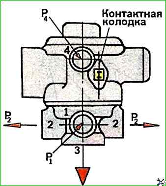
To dismantle piston 15, it is necessary to supply air under a pressure of 0.05 MPa to outlet 4 (see Fig. 2).
Unscrew the housing fastening bolts 20; 4 and covers 5, remove housing 20 and cover 5, plates 7, membrane 6 and spring 8.
To dismantle the electromagnet, unscrew the screws securing the exhaust valve seat 1, remove the exhaust valve seat from housing 4 together with valve 30 and adjusting linings 2.
To disassemble the valve, remove thrust ring 32 securing housing 31 using round-nose pliers.
To dismantle the electromagnet, first unscrew the screws securing the plug connector and unsolder wires 34 and remove the electromagnet assembly from housing 4.
Valve 10 can be dismantled from housing 4 by removing thrust ring 14, cover 13 and thrust ring securing valve housing 9 using round-nose pliers.
The modulator electromagnet cannot be disassembled and is replaced entirely in in case of its failure.
After disassembling, the modulator parts must be washed, dried and carefully inspected.
There must be no cracks, hairlines or other defects visible to the eye on the surface of the body parts.
The parts must be cleaned of rust and burnt-on deposits.
All rubber parts must be replaced with new ones.
Before assembling, the modulator parts must be lubricated with a thin layer of TSIA-TIM-221 grease.
The assembly of valves, rubber sealing rings and other rubber parts must be carried out carefully, preventing their damage.
The presence of scratches, cuts and other defects on the surface of these parts is not allowed.
The modulator is assembled in the reverse order of disassembly.
When assembling, keep in mind that terminal 1 (see Fig. 2) housing 20 must be in the same plane with terminal 4 of housing 4.
When installing the electromagnet in housing 4, after installing it, first install the seat of the exhaust valve 1 without adjusting shims 2 and measure the gap "h" with a feeler gauge.
Then select the shims using the table.
The minimum allowable gap should be 0.5 mm.

Checking the modulator ABS for operability
Install the modulator on the test bench and connect it according to the diagram shown in Fig. 2.
Supply air under pressure P1 = 0.75 MPa to terminal 1.
Supply and release air under pressure P4 = 0.75 MPa to terminal 4 three times. The air pressure in terminal 2 should change from zero to 0.75 MPa and back.
Increase the pressure in terminal 2 from zero to 0.75 MPa and back.
Increase the pressure in terminal 4 to P4 = 0.03-0.04 MPa, pressure should appear in terminal 2.
With a further increase in pressure in terminal 4 to P4 = 0.66 - 0.70 MPa, the pressure in terminal 2 should become P2 = 0.73 MPa.
When the pressure in pin 4 drops to zero, the pressure in pin 2 should also drop to zero.
Stepwise pressure change for all is should not exceed 0.02 MPa during tests.
The valve tightness test is performed in two positions: with a pressure of 0.75 MPa in terminal 1; with a pressure of 0.75 MPa in terminals 1 and 4.
There should be no leakage in either position.
Apply air under pressure P1 and P4 = 0.75 MPa to terminals 1 and 4.
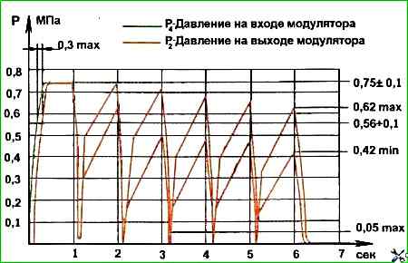
Apply five rectangular signals of 11 V, 0.2 s duration, 1 s intervals, to the contact block.
The change in pressure P2 in the container connected to any of terminals 2 should correspond to the change in pressure shown in Figure 2.
")

")
")
")
")
")
")
")